


MJ-1103/1104 © 2008, 2009 TOSHIBA TEC CORPORATION All rights reserved
DISASSEMBLY AND INSTALLATION
4 - 48
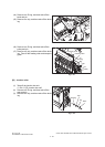
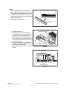
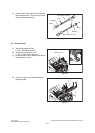
[E] Entrance roller
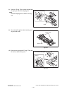
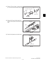
(7) Remove each 2 E-rings from the front and
rear transport rollers. Then remove 2 bush-
ings, the pulley and the pin.
Fig. 4-132
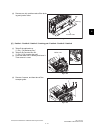
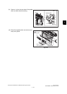
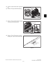
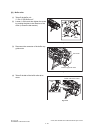
(1) Take off the stationary tray.
P.4-1 "[A] Stationary tray"
(2) Take off the Junction box unit.
P.4-13 "[A] Junction box unit"
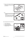
(3) Close the buffer unit-1 halfway and leave it.
Then remove 1 screw.
Fig. 4-133
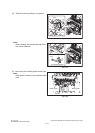
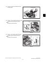
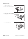
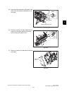
(4) Remove 3 screws, and then take off the
transport guide.
Fig. 4-134
Front transport roller
Pulley
Pulley
Bushing
Bushing
Pin
Pin
Rear transport roller
Buffer unit-1
Screw
Transport guide