


4
© 2008, 2009 TOSHIBA TEC CORPORATION All rights reserved MJ-1103/1104
DISASSEMBLY AND INSTALLATION
4 - 31
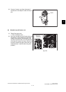
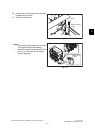
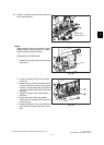
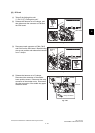
(4) Remove 4 screws and take off the upper sta-
pler frame assembly.
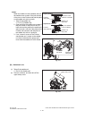
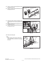
Notes:
When installing, adjust the position of each
saddle stapler clinch unit using an exclusive
jig following the procedure below.
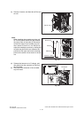
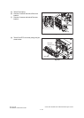
6LB296160 JIG-STAPLE-SDL
1. Install the jig on the hole of the lower sta-
pler frame.
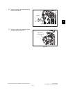
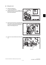
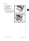
2. Loosen 3 screws fixing the front stapler
clinch unit.
3. Rotate the gear of the front stapler clinch
unit in the direction of the arrow to pull out
the clinch. Keep rotating the gear until the
clinch is inserted all the way into the hole
of the jig.
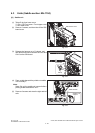
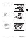
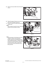
4. Tighten 3 screws in the order shown in
the figure.
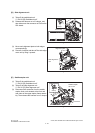
5. Return the clinch of the front stapler
clinch unit to its original position and then
remove the jig.
6. Adjust the position of the rear saddle sta-
pler clinch unit following the same proce-
dure.
Fig. 4-85
Fig. 4-86
Fig. 4-87
Upper stapler
frame assembly
Jig
Hole
Clinch
GearHole of the jig