


4
© 2008, 2009 TOSHIBA TEC CORPORATION All rights reserved MJ-1103/1104
DISASSEMBLY AND INSTALLATION
4 - 89
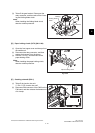
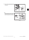
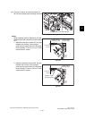
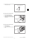
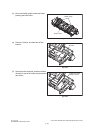
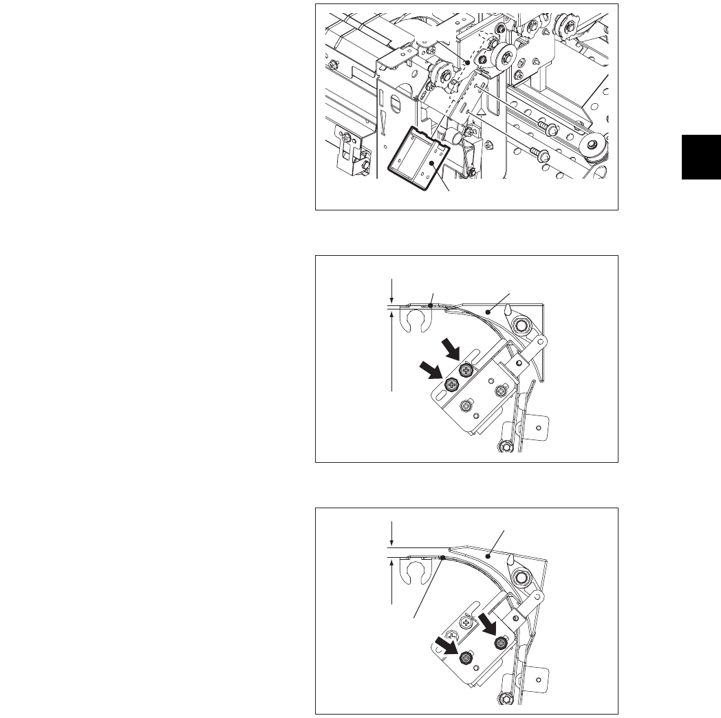
(13) Remove 2 screws, and remove the arm to
take off the transport path switching solenoid.
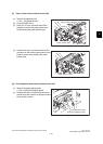
Notes:
When installing, perform adjustment for both
cases in which the solenoid is turned ON and
OFF.
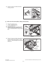
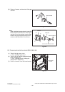
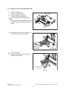
1. When the solenoid is turned OFF, the gap
between the surface of the transport
guide and the upper side of the flap edge
must fall within 1.5 mm to 2.1 mm. Fix the
solenoid with 2 screws.
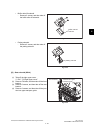
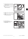
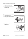
2. When the solenoid is turned ON, the gap
between the surface of the transport
guide and the upper side of the flap edge
must fall within 2.3 mm to 2.9 mm. Fix the
solenoid with 2 screws.
Fig. 4-249
Fig. 4-250
Fig. 4-251
Transport path switching solenoid
Arm
Upper side of
the flap edge
Surface of the
transport guide
1.5mm to
2.1mm
Upper side of
the flap edge
Surface of the
transport guide
2.3mm to
2.9mm