


3
© 2008, 2009 TOSHIBA TEC CORPORATION All rights reserved MJ-1103/1104
DESCRIPTION OF OPERATIONS
3 - 37
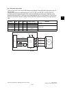
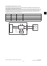
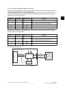
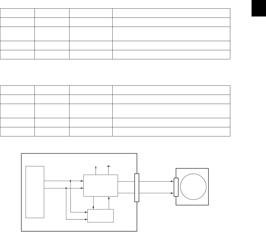
[C] Front / Rear saddle stapler motor drive circuit
The front / rear saddle stapler motor drive circuit controls the rotation and stoppage, rotational direction
and motor current of the front / rear saddle stapler motor.
The front saddle stapler motor is a DC motor which is driven by rotation control signals (DM2-CNT1 and
DM2-CNT0) from the CPU of the saddle control PC board, and thus this motor performs a stapling
operation of the front saddle stapler.
The rear saddle stapler motor is a DC motor which is driven by rotation control signals (DM3-CNT1 and
DM3-CNT0) from the CPU of the saddle control PC board, and thus this motor performs a stapling
operation of the rear saddle stapler.
For the case when an overcurrent status is detected, a protection circuit is mounted to turn the front /
rear saddle stapler motor off.
Fig. 3-43
DM2-CNT1 DM2-CNT0 Motor rotation Remarks
L H Normal Operates the stapler.
H L Reverse Initial operation
(Only when the stapler operates abnormally.)
HH Stop
LL Stop
DM3-CNT1 DM3-CNT0 Motor rotation Remarks
L H Normal Operates the stapler.
H L Reverse Initial operation
(Only when the stapler operates abnormally.)
HH Stop
LL Stop
IC31
CPU
DM2/3-CNT0
DM2/3-F
VM5VPA
Front saddle
stapler motor
(M18)
Rear saddle
stapler motor
(M19)
Motor drive circuit
Saddle control PC board
Overcurrent
protection circuit
DM2/3-R
DM2/3-CNT1
CN6/7