


MJ-1103/1104 © 2008, 2009 TOSHIBA TEC CORPORATION All rights reserved
DESCRIPTION OF OPERATIONS
3 - 32
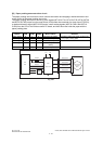
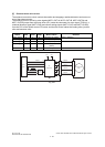
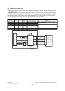
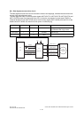
[J] Paddle motor drive circuit
The paddle motor drive circuit controls the rotation and stoppage, rotational direction and motor current
of the paddle motor.
The paddle motor is driven by pulse signals (MOT3-OUT1A, MOT3-OUT1B, MOT3-OUT2A and MOT3-
OUT2B) output from the motor driver (IC2) under the command of a clock signal (TIOCC3), a rotational
direction signal (MOT3-DIR) and a current setting signals (MOT3-CUR1 and MOT3-CUR0) from the
CPU of the finisher control PC board, and thus this motor rotates the paddle.
Fig. 3-37
TIOCC3
MOT3-
DIR
MOT3-
CUR1
MOT3-
CUR0
Motor rotation Remarks
Clock signal H L H Normal (Low power) Paper is pulled into the finishing position
and then pushed off.
Clock signal H L L Normal (Normal power)
Clock signal L L H Reverse (Low power) Eliminates backlash.
Clock signal L L L Reverse (Normal
power)
--H- Stop
IC21
CPU
TIOCC3
MOT3-OUT1A
VM
MOT3-OUT2A
MOT3-OUT1B
MOT3-OUT2B
SG
MOT3-DIR
24
4
1
21
5
20
16
13
P-RESET
P-RESET
3.3V
Paddle motor
(M3)
IC2
Motor driver
Finisher control PC board
MOT3-CUR1
17
MOT3-CUR0
Current
control
circuit
CN22