


E6581381
F-6
6
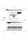
• Function
Use the above parameters to send signals from an external programmable controller to various control
input terminals to operate and/or set the inverter.
The desired contact input terminal functions can be selected from 57 types (0 to 71). This gives system
design flexibility.
• The functions of the VIA terminal can be selected between analog input and contact input by changing
parameter settings
H.
To use the VIA terminal as contact input terminals, you need to set
H to the number (1 or 2) that
suits your needs, since analog input (voltage signal input) is assigned to the terminals by default.
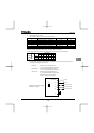
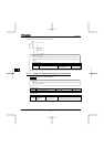
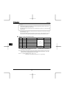
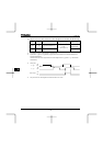
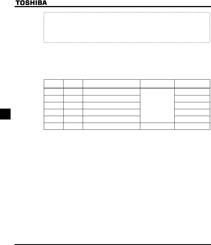
■ Setting of contact input terminal function
Terminal
symbol
Title Function Adjustment range Default setting
-
H
Always-active function selection 1 0
-
H
Always-active function selection 2 1 (ST)
F
H
Input terminal selection 1 (F) 2 (F)
R
H
Input terminal selection 2 (R) 3 (R)
RES
H
Input terminal selection 3 (RES)
0-71
(
⇒ See page K-15)
10 (RES)
VIA
H
Input terminal selection 8 (VIA)
0-71 Note 2)
6 (SS1)
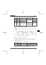
Note 1: The function that has been selected using H and H (always-active function selection
parameter) are always activated.
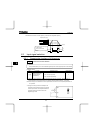
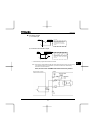
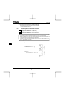
Note 2: When using the VIA terminal as contact input terminals in sink logic connection, be sure to insert a
resistor between the P24 terminal and the VIA terminal. (Recommended resistance: 4.7k
Ω-1/2W)
Be sure to turn the VIA (SW3) slide switch to the V position.
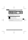
Note 3:
H (VIA): Enabled only when H= or
Disabled and the set value cannot be read out, if H is set at .