


E6581381
E-5
5
Coast stop (CW=)
Setting for coast stopping. In sink logic mode, closing the circuit between the R and CC terminals places the
inverter in standby mode and opening the circuit places it in coast stop mode, because ST (standby signal)
is assigned to the R terminal.
⇒ See section 3.1.1 (3) and 6.3.1 for details.
3-wire operation (CW=)
Can be operated by a momentary push-button. HD (operation holding) is assigned to the terminal R. A self-
holding of operations is made in the inverter by connecting the stop switch (b-contact) to the R terminal and
connecting the running switch (a-contact) to the F terminal.
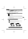
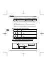
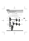
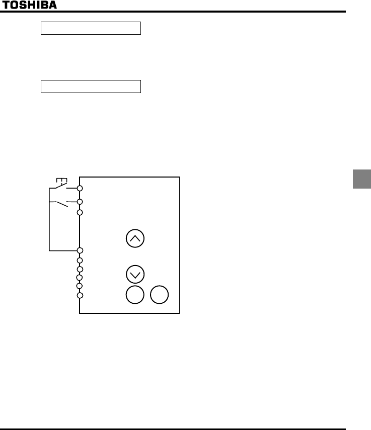
+ Three-wire operation (one-touch operation)
You can carry out operation by simply pressing the ON/OFF button.
Standard connection diagram- Forward run
Selecting HD (operation holding) with the input
terminal selection parameter
Select HD (operation holding) using the input
terminal selection parameter, and turn HD on to
get the inverter ready for operation or turn HD
off to stop operation.
Parameter setting:
When parameter CWis set to , the following
parameters are set automatically.
H : (ST)
EOQF : (terminal board).
R terminal H : (operation holding).
Note 1 : Even if each terminal is ON, any command entered
through a terminal is ignored when power is turned
on (to prevent the load from starting to move
unexpectedly). Enable to turn the input terminal on
at power on.
Note 2 : When HD is OFF, any attempt to turn on F is
ignored.
Note 3 : Sending out a RUN signal during DC braking has
no effect in stopping DC braking.
F
R (HD)
RES
CC
PLC
PP
VI
A
VIB
CC
STOPRUN