


E6581381
L-3
12
<Continued>
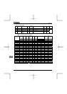
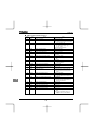
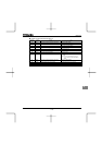
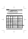
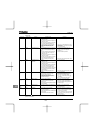
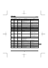
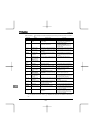
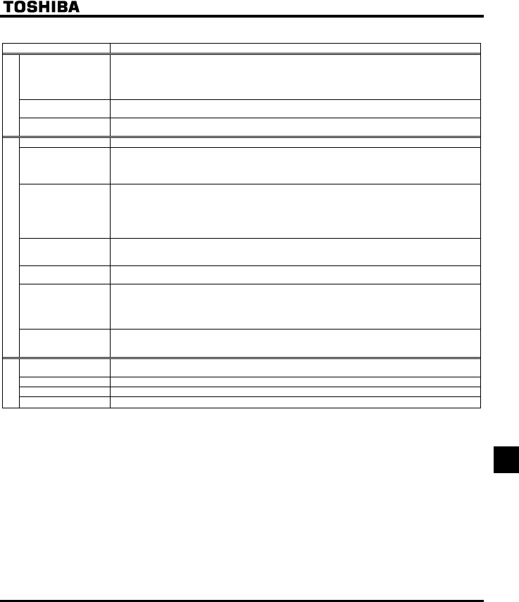
Item Specification
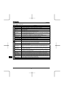
Protective function Stall prevention, current limitation, over-current, output short circuit, over-voltage, over-voltage limitation,
undervoltage, ground fault, power supply phase failure, output phase failure, overload protection by
electronic thermal function, armature over-current at start-up, load side over-current at start-up, over-
torque, undercurrent, overheating, cumulative operation time, life alarm, emergency stop, various pre-
alarms
Electronic thermal
characteristic
Switching between standard motor and constant-torque VF motor, switching between motors 1 and 2,
setting of overload trip time, adjustment of stall prevention levels 1 and 2, selection of overload stall
Protective function
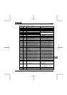
Reset function Function of resetting by closing contact 1a or by turning off power or the operation panel. This function is
also used to save and clear trip records.
Alarms Stall prevention, overvoltage, overload, under-voltage, setting error, retry in process, upper/lower limits
Causes of failures Over-current, overvoltage, overheating, short-circuit in load, ground fault, overload on inverter, over-
current through arm at start-up, over-current through load at start-up, CPU fault, EEPROM fault, RAM
fault, ROM fault, communication error. (Selectable: Emergency stop, under-voltage, low voltage, over-
torque, motor overload, output open-phase)
Monitoring function Operation frequency, operation frequency command, forward/reverse run, output current, voltage in DC
section, output voltage, torque, torque current, load factor of inverter, input power, output power,
information on input terminals, information on output terminals, version of CPU1, version of CPU2,
version of memory, PID feedback amount, frequency command (after PID), integral input power, integral
output power, rated current, output speed, communication counter, normal state communication counter,
causes of past trips 1 through 4, parts replacement alarm, cumulative operation time
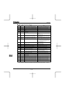
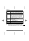
Past trip monitoring
function
Stores data on the past four trips: number of trips that occurred in succession, operation frequency,
direction of rotation, load current, input voltage, output voltage, information on input terminals, information
on output terminals, and cumulative operation time when each trip occurred.
Output for frequency
meter
Analog output: (1mAdc full-scale DC ammeter or 7.5Vdc full-scale DC ammeter / Rectifier-type AC
voltmeter, 225% current Max. 1mAdc, 7.5Vdc full-scale), 4 to 20mA/0 to 20mA output
4-digit 7-segments LED Frequency: inverter output frequency.
Alarm: stall alarm “C”, overvoltage alarm “P”, overload alarm “L”, overheat alarm “H”.
Status: inverter status (frequency, cause of activation of protective function, input/output voltage,
output current, etc.) and parameter settings.
Free-unit display: arbitrary unit (e.g. rotating speed) corresponding to output frequency.
Display function
Indicator
Lamps indicating the inverter status by lighting, such as RUN lamp, MON lamp, PRG lamp, % lamp, Hz
lamp, LOC/REM key lamp, UP/DOWN key lamp and RUN key lamp. The charge lamp indicates that the
main circuit capacitors are electrically charged.
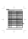
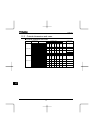
Use environments Indoor, altitude: 1000m (Max.), not exposed to direct sunlight, corrosive gas, explosive gas or vibration
(less than 5.9m/s
2
) (10 to 55Hz)
Ambient temperature -10 to +60°C Note1) Note2)
Storage temperature -20 to +65°C
Environments
Relative humidity 20 to 93% (free from condensation and vapor).
Note 1: Above 40°C: Remove the seal from the top of the inverter and use the inverter with the rated output current reduced.
Note 2: If inverters are installed side by side (with no sufficient space left between them): Remove the seal from the top of
each inverter.
When installing the inverter where the ambient temperature will rise above 40°C, remove the seal from the top of the
inverter and use the inverter with the rated output current reduced.