


E6581381
E-26
5
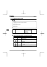
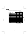
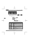
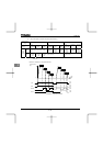
■ Setting of electronic thermal protection characteristics selection QNO
Setting value Overload protection Overload stall
{
×
{{
××
×
{
{ : valid, × : invalid
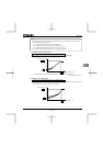
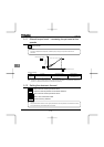
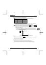
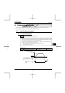
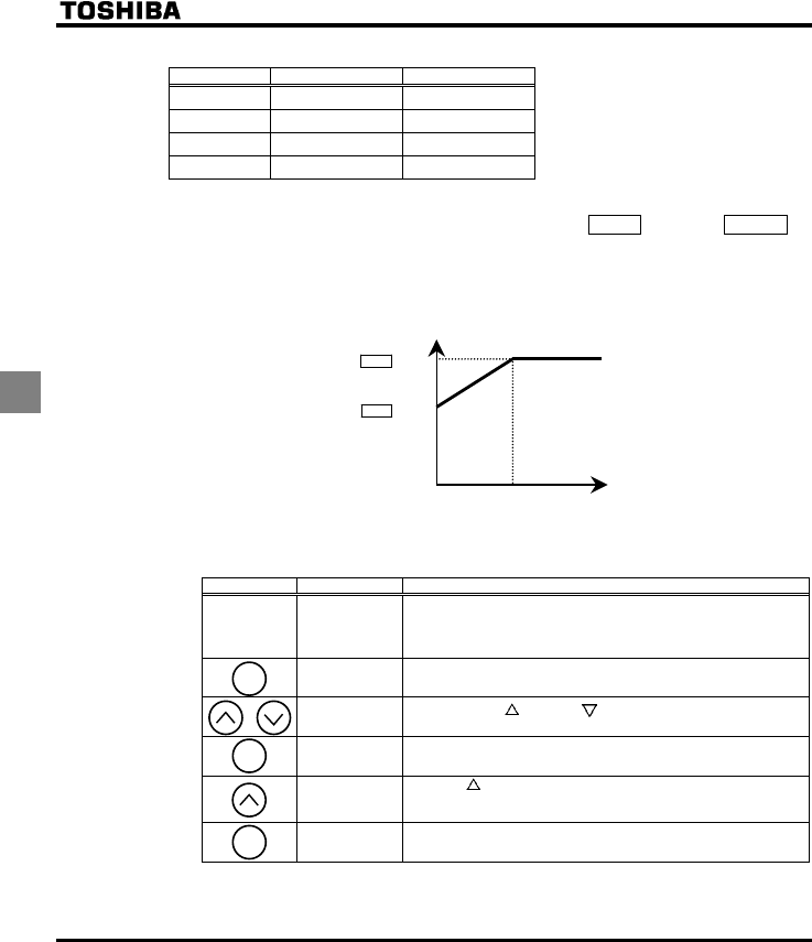
■ Setting of motor electronic thermal protection level 1 VJT (Same as H)
If the capacity of the motor is smaller than the capacity of the inverter, or the rated current of the motor
is smaller than the rated current of the inverter, adjust the electronic thermal protection level 1 VJT so
that it fits the motor's rated current.
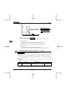
VJT
×0.55
VJT
×1.0
Output frequency (Hz)
Output current reduction factor
[%]/[A]
0
30Hz
Note: The motor overload protection start level is fixed at 30Hz.
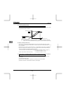
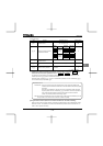
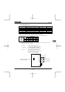
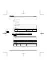
[Example of setting: When the VFFS1-2007PM is running with a 0.4kW motor having 2A rated current]
Key operated LED display Operation
Displays the operation frequency. (Perform during operation
stopped.)
(When standard monitor display selection H is set to
[Operation frequency])
CWH
The first basic parameter “CWH” (Wizard function) is displayed.
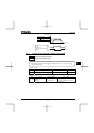
VJT
Press either the key or the key to change the parameter to
VJT.
Press the ENT key to display the parameter setting. (Standard
default setting: 100%)
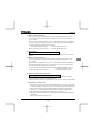
Press the key to change the parameter to %
(=motor rated current/inverter output rated current x
100=2.0//4.8×100).
¶⇔¶VJT
Press the ENT key to save the changed parameter. VJT and the
parameter are displayed alternately.
Note: The rated output current of the inverter should be calculated from the rated current, regardless of the
setting of the PWM carrier frequency parameter (H).
MODE
ENT
ENT