


E6581381
A-16
1
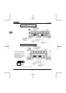
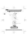
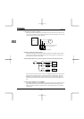
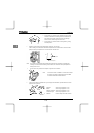
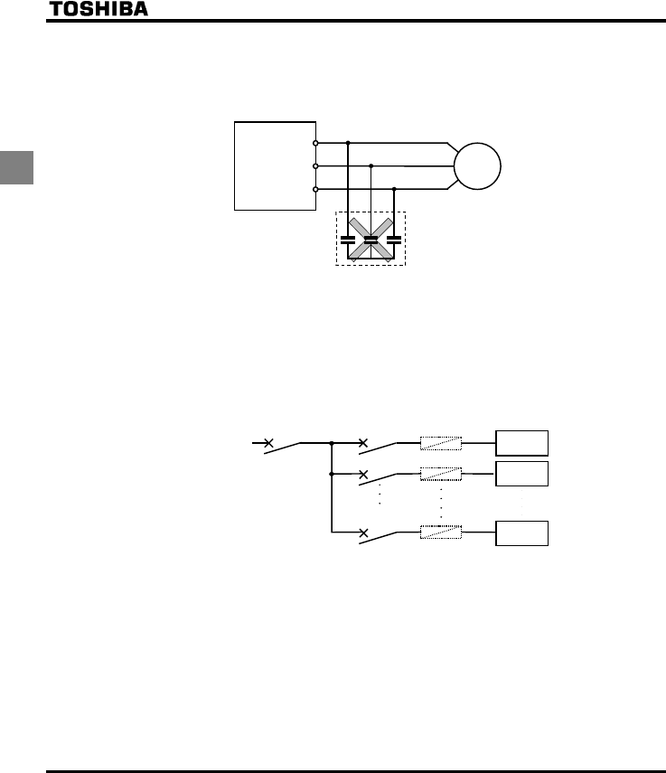
Power factor correction capacitor
Power factor correction capacitors cannot be installed on the output side of the inverter. When a motor
is run that has a power factor correction capacitor attached to it, remove the capacitors. This can cause
inverter malfunction trips and capacitor destruction.
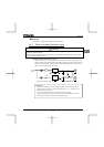
Remove the power factor correction
capacitor and surge absorber
Power factor correction capacitor
U
/
T1
V
/
T2
W
/
T3
Inverte
r
IM
Operating at other than rated voltage
Connections to voltages other than the rated voltage described in the rating label cannot be made. If a
connection must be made to a power supply other than one with rated voltage, use a transformer to
raise or lower the voltage to the rated voltage.
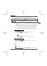
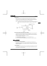
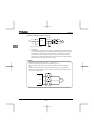
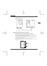
Circuit breaking when two or more inverters are used on the same power line.
MCCB1
MCCBn
+
1
MCCB3
MCCB2
INV1
INV2
INVn
(circuit breaking fuse)
Breaking of selected inverter
There is no fuse in the inverter's main circuit. Thus, as the diagram above shows, when more than one
inverter is used on the same power line, you must select interrupting characteristics so that only the
MCCB2 will trip and the MCCB1 will not trip when a short occurs in the inverter (INV1). When you
cannot select the proper characteristics install a circuit interrupting fuse between the MCCB2 and the
INV1.
If power supply distortion is not negligible
If the power supply distortion is not negligible because the inverter shares a power distribution line with
other systems causing distorted waves, such as systems with thyristors or large-capacity inverters,
install an input reactor to improve the input power factor, to reduce higher harmonics, or to suppress
external surges.