


E6581381
A-4
1
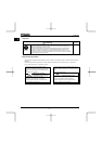
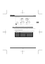
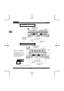
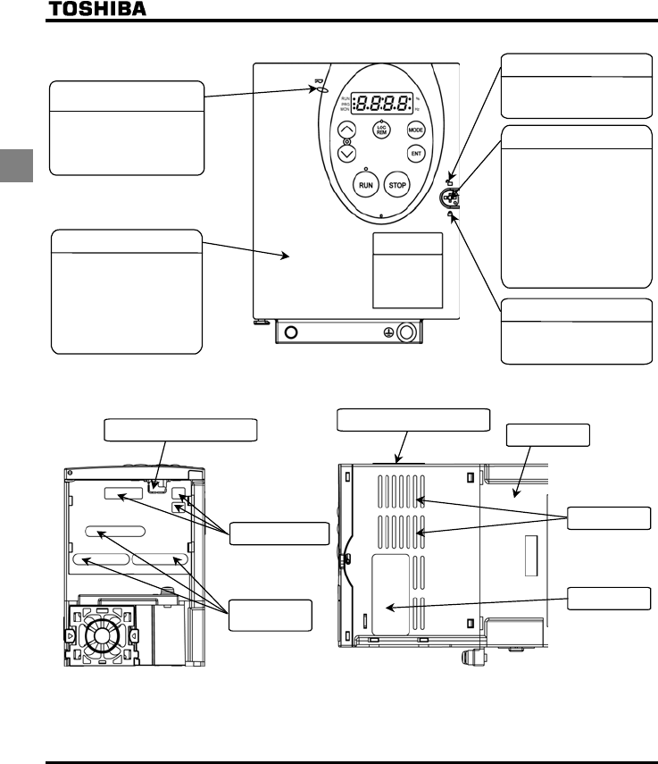
The front panel is unlocked when
the dot on the locking screw is on
this (upper) side.
The front panel is locked when the
dot on the locking screw is on this
(lower) side.
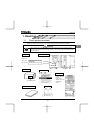
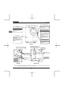
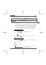
[Front]
Charge lamp
Front panel
Indicates that high voltage is still
present within the inverter. Do not
open the terminal board cover
while this is lit.
The front panel of the inverter or
terminal board
To avoid touching the terminal
board by mistake, be sure to close
the front panel before starting
operation.
Front panel locking screw
The inverter came with this
screw in the locked position.
So from this position, turn the
screw 90° counterclockwise to
unlock the front panel, or turn
it 90° clockwise to lock the
front panel.
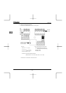
The screw does not turn 360°. To
avoid damage to the screw, do
not use excessive force when
turning it.
Unlock position mark
Lock position mark
To
p
warnin
g
label Note
)
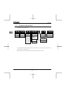
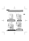
Colling fin
Communicatio Connector hole
Cnotrol cable port
Ventilation slit
Name plate
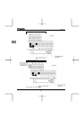
[Bottom]
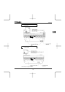
[Right side]
Main circuit
cable port
Note: Remove this seal and operate it at a current lower than the rated one when installing the inverter side by side with
other inverters where the ambient temperature will rise above 40°C.