


E6581381
H-2
8
(Continued)
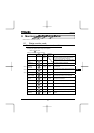
Item displayed
Key
operated
LED
display
Communic
ation No.
Description
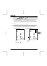
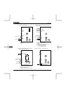
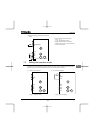
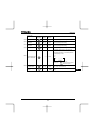
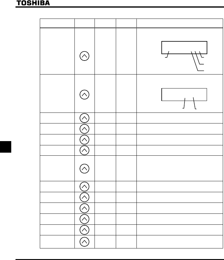
Input terminal
__KK
FE06
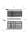
The ON/OFF status of each of the control signal
input terminals (F, R, RES and VIA) is displayed in
bits.
ON:
OFF: _
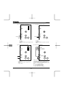
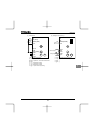
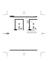
Output terminal _K FE07
The ON/OFF status of each of the control signal
output terminals (RY and FL) is displayed in bits.
ON:
OFF: _
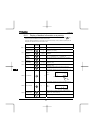
CPU1 version
X
FE08 The version of the CPU1 is displayed.
CPU2 version
XY
FE73 The version of the CPU2 is displayed.
Memory version
XG
FE09 The version of the memory mounted is displayed.
PID feedback
F
FE22 The PID feedback value is displayed. (Hz/free unit)
Frequency
command value
(PID-computed)
D
FE15
The PID-computed frequency command value is
displayed. (Hz/free unit)
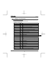
Integral input
power
M
FE76
The integrated amount of power (kWh) supplied to
the inverter is displayed.
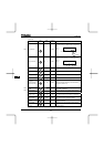
Integral output
power
J FE77
The integrated amount of power (kWh) supplied
from the inverter is displayed.
Rated current
C
FE70 The rated current of the inverter (A) is displayed.
Output speed FE90
Displays the motor speed ( min-1) by calculating
with output frequency and pole numbers.
Communication
counter
O
FA15
Displays the counter numbers of communication
through the network.
Normal state
communication
counter
P FA16
Displays the counter numbers of communication
only at normal state in the all communication
through network.
(Continued overleaf)
_K
RY-RC
FL
Note 5
Note 5
Note 4
__KK
VIA
F
R
RES