


E6581381
B-6
2
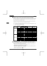
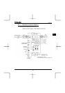
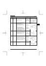
■ Power circuit
Terminal symbol Terminal function
Grounding terminal for connecting inverter. There are 3 terminals in total. 2 terminals in
the terminal board, 1 terminal in the cooling fin.
R/L1,S/L2,T/L3
200V class: three-phase 200 to 240V-50/60Hz
400V class: three-phase 380 to 480V-50/60Hz
U/T1,V/T2,W/T3
Connect to a (three-phase induction) motor.
PA/+, PC/-
PA/+ terminal: Positive potential terminal for the internal DC main circuit
PC/- terminal: Negative potential terminal for the internal DC main circuit
DC power can be supplied through the PA/+ and PC/- terminals.
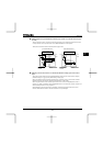
The arrangement of power circuit terminals are different from each range.
⇒ See section 1.3.2.1) about the arrangement of power circuit terminals.
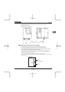
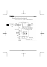
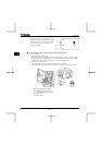
2.3.2 Control circuit terminals
The control circuit terminal board is common to all equipment.
Regarding to the function and specification of each terminal, please refer to the following table.
⇒ See section 1.3.2.3) about the arrangement of control circuit terminals.
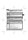
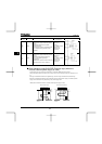
■ Control circuit terminals
Terminal
symbol
Input/output Function
Electrical
specifications
Inverter internal circuits
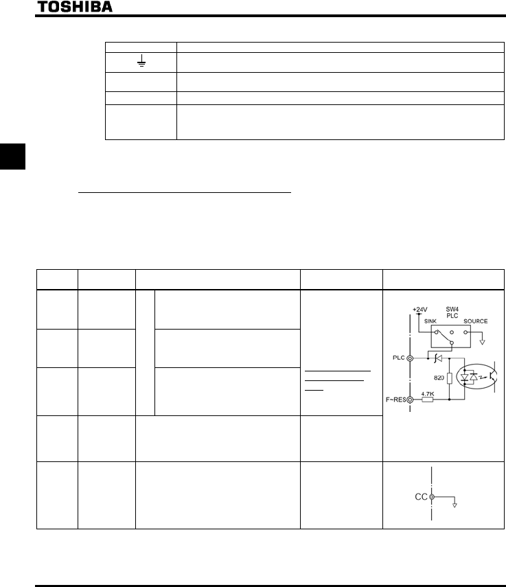
F Input
Shorting across F-CC causes
forward rotation; open causes slow-
down and stop. (When ST is always
ON)
R Input
Shorting across R-CC causes
reverse rotation; open causes slow-
down and stop. (When ST is always
ON)
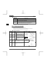
RES Input
Multifunction programmable
contact in
p
ut
This inverter protective function is
disabled if RES are CC is connected.
Shorting RES and CC has no effect
when the inverter is in a normal
condition.
No voltage
contact input
24Vdc-5mA or less
*Sink/Source/PLC
selectable using
SW4
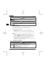
PLC
Input
(common)
External 24Vdc power input
When the source logic is used, a common
terminal is connected.
24VDC
(Insulation
resistance: DC50V)
Factory default setting
WN type : SINK side
WP type : SOURCE side
CC
Common to
Input/output
Control circuit's equipotential terminal (2
terminals)