


E6581381
H-8
8
(Continued)
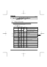
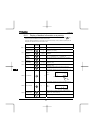
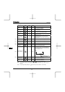
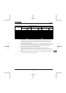
Item displayed
Key
operated
LED
display
Communic
ation No.
Description
Integral output
power
J FE77
The integrated amount of power (kWh) supplied
from the inverter is displayed.
(0.01=1kWh, 1.00=100kWh)
Rated current
C
FE70
The inverter rated current (A) at the occurrence of
a trip is displayed.
Output speed
FE90
Displays the motor speed ( min-1) by calculating
with output frequency and pole numbers.
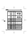
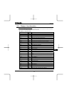
Communication
counter
O FA15
Displays the counter numbers of communication
through the network.
Note that they are current values, not at tripping.
Normal state
communication
counter
P
FA16
Displays the counter numbers of communication
only at normal state in the all communication
through network.
Note that they are current values, not at tripping.
Past trip 1
QR ⇔
FE10 Past trip 1 (displayed alternately)
Past trip 2
QJ ⇔
FE11 Past trip 2 (displayed alternately)
Past trip 3
QR ⇔
FE12 Past trip 3 (displayed alternately)
Past trip 4
PGTT ⇔
FE13 Past trip 4 (displayed alternately)
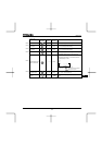
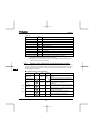
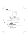
Parts replacement
alarm information
O___K
FE79
The ON/OFF status of each of the cooling fan,
circuit board capacitor, main circuit capacitor of
parts replacement alarm or cumulative operation
time are displayed in bits.
ON:
OFF: _
Cumulative
operation time
V FE14
The cumulative operation time is displayed.
(0.01=1 hour, 1.00=100 hours)
Default display
mode
QR
The cause of the trip is displayed.
Note 1: Items displayed can be changed by pressing or key in the each monitor mode.
Note 2: You can switch between % and A (ampere)/V (volt), using the parameter H (current/voltage unit
selection).
Note 3: The input (DC) voltage displayed is 1
2
times as large as the rectified d.c. input voltage.
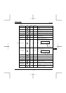
Note 7
Note 8
Note 6
Note 6
Note 6
Note 6
O
___K
C
oolin
g
fan
o
p
eration time
Control circuit board ca
p
acitor
Main circuit ca
p
acitor
MODE