E6581381
F-42
6
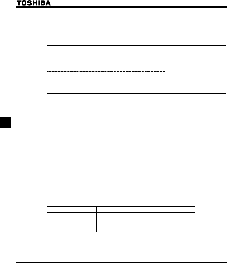
2) Types of PID control interfaces
Process quantity input data (frequency) and feedback input data can be combined as follows for the PID
control of the VF-FS1:
Process quantity input data (frequency setting)
Feedback input data
Setting method
Frequency setting mode selection
HOQF / H
PID control
H
(1) External analog setting
VIA (DC: 4-20mA / 0-10V)
(2) External analog setting
VIB (DC: 0-10V)
(3) Panel input setting Internal
preset-speed setting
(4) Serial communication
(5) UP/DOWN from external
contact
(6) Internal preset-speed setting - (EOQF=0)
: External analog input
VIA (DC:4-20mA / DC:0-10V)
: External analog input
VIB (DC:0-10V)
Note 1: About the setting of HOQF and H: Do not select the same terminal that is used feedback
terminal (VIA or VIB).
Note 2: When using VIA terminal, set
H or H respectively to 52 or 53 to put out signals to RY-RC
or FLA-FLB-FLC.
When using VIB terminal, set
H or H respectively to 60 or 61 to put out signals to RY-RC
or FLA-FLB-FLC.
You can also specify a frequency agreement detection range (
H).
⇒ For more information, see section 6.3.5.
3) Setting PID control
Set "" or "2" in the extended parameter H (PID control)
(1) Set parameters CEE(acceleration time), and FGE (deceleration time) to the system fitting values.
(2) To limit the output frequency, set parameters
WN (upper limit frequency) and NN (lower limit
frequency). If process quantities are set from the operation panel, however, the process quantity setting
range will be limited by the settings of
WN and NN.
4) Adjusting the PID control gain level
Adjust the PID control gain level according to the process quantities, the feedback signals and the object to
be controlled.
The following parameters are provided for gain adjustment:
Parameter Setting range Default setting
H (P-gain) 0.01-100.0 0.30
H (I-gain) 0.01-100.0 0.20
H (D-gain) 0.00-2.55 0.00


