ADCP-61-471 • Issue 4 • June 2000 • Section 2: Operation and Maintenance
2-80
© 2000, ADC Telecommunications, Inc.
DLP-524
Page 5 of 5
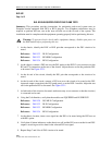
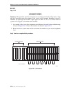
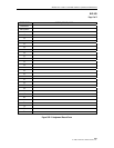
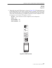
5. If the LED indicators respond as described, proceed to Step 6; otherwise, refer to the
following to isolate the problem:
STATUS is red
— The RLXIOR module has failed self-test diagnostics. Remove and
reinsert the module, then wait while it again performs self-test diagnostics. If the
STATUS LED turns red at the end of the second self-test, the module is defective;
replace the module, then repeat Steps 1 through 4.
NET LOS/BER is red
— A DS1 signal is not being received from the network.
NET LOS/BER is yellow
— The error rate of the DS1 network signal exceeds the
threshold value (default value is 10–7).
LINE LOS/BER is red
— A DS1 signal is not being received from the line.
LINE LOS/BER is yellow
— The error rate of the DS1 line signal exceeds the
threshold value (default value is 10–7).
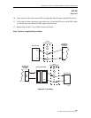
6. Press the LMPTST switch on the APU to verify that all the LEDs on the front panel of the
RLXIOR light yellow. This indicates that the LEDs are functional. If all LEDs do not light
yellow, the module is defective; replace the module, then repeat Steps 1 through 6.
Note:
The MPU must be installed in the chassis for Step 6 to work.
7. Repeat this entire procedure for each RLXIOR module.
Stop! You have completed this procedure.


