ADCP-61-471 • Issue 4 • June 2000 • Section 2: Operation and Maintenance
2-107
© 2000, ADC Telecommunications, Inc.
DLP-532
Page 2 of 3
6126-C
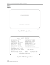
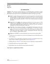
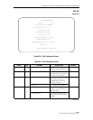
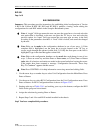
DLX CONFIGURATION
Group: 5 Slot: 1
Unit Equip State: EQUIPPED
Unit Service State: IS
T1 Provision: YES
T1 Service State: OOS
T1 Line Code: AMI
Pulse Equalization: 0-133 FT.
T1 BER Threshold: 1E-7
Loopback Timeout Period: 0 minutes
Circuit ID:
Press CONTROL-A For Assistance
Figure 532-1. DLX Configuration Screen
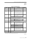
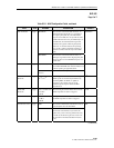
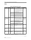
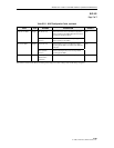
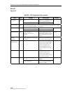
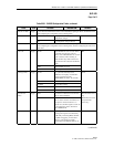
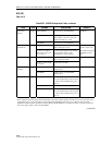
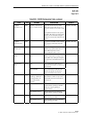
Table 532-1. DLX Configuration Fields
FIELD TYPE OPTIONS DESCRIPTION DEFAULT
Group Toggle 1, 2, 3, 4, 5, 6, or 7 Specifies the module’s group
number designated on the chassis.
1
Slot Toggle 1, 2, 3, or 4 Specifies the module’s slot number
designated on the chassis. Refer to
TAD-106 (Access Identifier).
1
Unit Equip State Toggle Equipped Establishes communication with
MPU. Module must be set to
EQUIPPED before remaining
selections are allowed.
UNEQUIPPED
Unequipped No communication with MPU.
Unit Service State Toggle IS (In-Service) Places the unit in service. This field
must be set to IS for reporting of
equipment alarms.
OOS
OOS (Out-Of-Service) Removes unit from service and
stops equipment alarm reporting by
the MPU.
(continued)


