


ADCP-61-471 • Issue 4 • June 2000 • Section 2: Operation and Maintenance
2-32
© 2000, ADC Telecommunications, Inc.
DLP-503
Page 1 of 1
APU INSTALLATION AND TESTING
Summary:
This procedure provides guidelines for installing and testing the APU.
Caution:
Modules can be damaged by electrostatic discharge (ESD). Before
handling any modules, ESD protection must always be used. An ESD grounding
post is located on the chassis for connecting the ESD wrist band. Ensure that all
modules removed from the equipment or not installed, are properly stored in anti-
static packing material. When working with modules, always place the module on
an electrically-grounded, approved, anti-static mat.
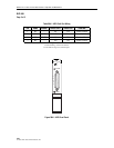
1. Remove the APU from protective packaging.
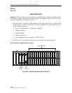
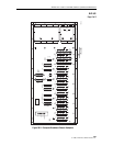
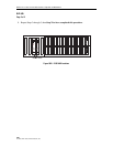
2. Push the APU into slot marked APU located in the upper right corner of the chassis.
3. Use screw to secure the APU to chassis.
4. If PWR indicator is not lighted at all, check for power at the A and B connections on the
backplane.
Reference:
DLP-508 –48 VDC Power Supply Test
5. If there is power at both of the connections (A and B), remove and replace the APU with a
new one.
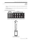
6. Press the LMPTST switch to verify that all APU indicators light. If any indicator does not
light, replace the APU.
Stop! You have completed this procedure.