


ADCP-61-471 • Issue 4 • June 2000 • Section 2: Operation and Maintenance
2-266
© 2000, ADC Telecommunications, Inc.
TAD-104
Page 1 of 11
TBOS INTERFACE DESCRIPTION
Summary:
This section provides information for operating the Soneplex Broadband system
using a Telemetry Byte Oriented Serial (TBOS) remote interface. The TBOS interface provides a
reliable means of communicating transmission alarm information between an Alarm Processing
telemetry Remote (APR) unit and the Soneplex Broadband system.
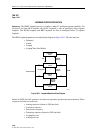
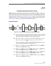
MPU
The MPU contains the processor, memory, and communication facilities to interface with a
centralized system administration control center. The MPU monitors the alarm/status conditions
of each module installed in the same chassis, as well as the alarm/status conditions of the remote
modules that are connected to them. The alarm/status conditions are saved in MPU memory for
transmission to the centralized administration center via TBOS protocol.
The MPU (Main Processing Unit) interfaces internally to the TBOS communications
link/protocol link to report alarm/status for local and remote modules, control and report
loopback configuration, and control and report protection switching status.
The MPU interfaces externally to a TBOS communications link/protocol. TBOS is the basic
communications format used by the customer-provided E2A-Alarm Processing telemetry
Remote (APR) equipment. The E2A-APR allows the concentration of up to 504 alarm
indications onto a four-wire alarm bus. The E2A-APR operates with a centralized alarm
surveillance/reporting system similar to the Bell Network Monitoring and Analysis (NMA)
System and TASC (Telecommunications Alarm Surveillance and Control) or the DFMS (Digital
Facility Maintenance System). AT&T Compatibility Bulletin 149 (CB-149) specifies the detailed
requirements of the E2A-APR.
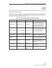
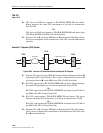
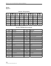
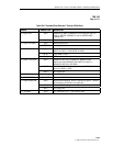
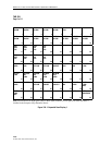
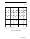
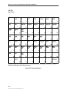
DS1 Signal Routing
Each DS1 signal corresponds to a specific mounting slot in the chassis. The DS1 signal and the
corresponding group-slot numbers are shown in Table 104-1.
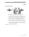
MPU TBOS Interface
The MPU TBOS interface is designed to meet AT&T CB-149, Section B2. Selection of hardware
port communication parameters and TBOS display options is performed through the Craft
Interface Serial Port Configuration screen.
Reference:
DLP-549 Serial Port Configuration
Information is transferred between the MPU and chassis modules via a synchronous
communication channel in the chassis backplane. The MPU polls each module for alarm and
status data and stores it into memory until requested by TBOS. Additionally, commands issued
by TBOS are passed through the MPU to the target module across this channel.