ADCP-61-471 • Issue 4 • June 2000 • Section 2: Operation and Maintenance
2-108
© 2000, ADC Telecommunications, Inc.
DLP-532
Page 3 of 3
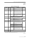
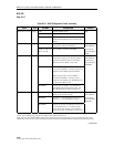
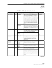
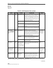
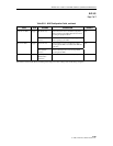
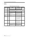
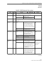
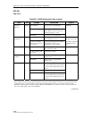
Table 533-1. DLX Configuration Fields, continued
FIELD TYPE OPTIONS DESCRIPTION DEFAULT
T1 Provision Toggle YES Brings up T1 default settings and
allows configuration changes.
NO
NO Prevents configuration settings.
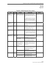
T1 Service State Toggle Leave this field at OOS at this time to avoid undesirable reporting of alarms. Place the circuit In-
Service after complete the remaining configurations.
T1 Line Code Toggle AMI Alternate Mark Inversion AMI
B8ZS Bipolar Eight-Zero Substitution
Pulse Equalization Toggle 0–133 ft., 133–266 ft.,
266–399 ft., 399–533 ft., or
533–655 ft.
The DS1 signal output provides
standard DSX signal levels which
can be compensated for various
distances.
0–133 ft.
T1 BER
Threshold
Toggle T1 BER Threshold can be set between
10
-3
and 10
-9
.
When the Bit Error Rate threshold
is exceeded, an alarm is triggered.
10
-7
Loopback
Timeout Period
Input Enter a number from 0 to 255. This field represents the number of
minutes that the loopback remains
in effect before reverting to the
normal (non-loopback) state.
Setting the loopback time-out
period to 0 disables the time-out
feature.
30
Circuit Identifier Input Up to 20 characters. This represents the customer’s
circuit ID. The first and last
characters must be alpha or
numeric; middle characters can be
alpha, numeric or hyphens.
None
T1 Service State Toggle IS (In-Service) Allows T1 alarms to be reported to
the MPU.
OOS
OOS (Out-Of-Service) Prevents T1 alarms from being
reported to the MPU.


