ADCP-61-471 • Issue 4 • June 2000 • Section 2: Operation and Maintenance
2-267
© 2000, ADC Telecommunications, Inc.
TAD-104
Page 2 of 11
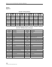
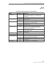
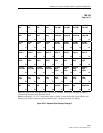
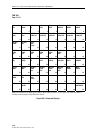
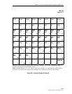
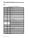
Table 104-2 (TBOS Abbreviations and Acronyms) and Table 104-3 (Expanded Scan Displays 2
Through 8 Definitions ) list the definitions of the abbreviations used in the TBOS displays shown
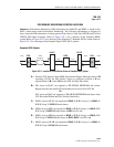
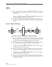
in Figure 104-1 (Expanded Scan Display 1), Figure 104-2 (Expanded Scan Displays 2 through
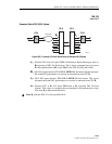
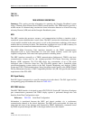
8), Figure 104-3 (Command Display 1), and Figure 104-4 (Command Displays 2 through 8). In
Figure 104-1, scan point (bit) 5, indicates a power alarm. In Figure 104-4, when TBOS issues a
command from command point 36 (D2 B8ZS), the module assigned to chassis group-slot 1-3
sets B8ZS line code on DS1 signal number two. Point 64 on the TBOS display is reserved.
Since the MPU module is used in both the Soneplex Loop Extender chassis and the Soneplex
Broadband chassis, some TBOS Scan and Command points apply only to modules used only in
the Soneplex Broadband chassis, such as the DS3 MUX module.
The MPU scans both the local and remote modules for presentation of alarm and status data to
TBOS. On the TBOS scan displays, active scan points are identified with a “1”. Inactive points
are shown by a “0”.
Commands issued from the Command Display affect any module installed in the chassis. These
TBOS commands perform the same function as the corresponding commands from the MPU
Craft Interface.
Scan Displays (Expanded)
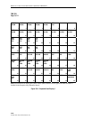
The MPU provides eight Scan Displays, one for the APU and MPU modules and seven for the
transmission portion of the chassis. Scan Display 1 shows conditions for the APU and MPU (see
Figure 104-1). Scan displays 2 through 8 provide scan points for chassis groups 1 through 7,
respectively (see Figure 104-2).
Command Displays
The MPU provides eight TBOS Command Displays for the chassis. Each command display
provides command points from which the TBOS operator can remotely provision the modules.
Command Display 1 shows command points for the APU and MPU (see Figure 104-3).
Command displays 2 through 8 provide command points for chassis groups 1 through 7,
respectively (see Figure 104-4).
Scan Displays (Compressed)
The MPU provides two Compressed Scan Displays, as shown in Figure 104-5 (Compressed Scan
Display 1) and Figure 104-6 (Compressed Scan Display 2), for a total of 126 scan bits plus two
reserved bits. Both displays are assigned a different display response address, in the range 0
through 7, through the MPU Craft Interface.


