


ADCP-61-471 • Issue 4 • June 2000 • Section 2: Operation and Maintenance
2-72
© 2000, ADC Telecommunications, Inc.
DLP-522
Page 1 of 2
DLX- OR RLX-EQUIPPED CIRCUIT END-TO-END TESTS
Summary:
This procedure provides instructions for performing end-to-end system tests on
Soneplex circuits equipped with DLX or RLX plug-ins. Two telephone technicians may be
required to perform this test, one at the near end and one at the far end of the system. The
installation must be complete and the equipment operating properly before performing this test.
Warning:
To prevent electric shock and/or equipment damage, disable span power at
the RLX module before performing this test.
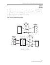
1. At the chassis, identify the DLX or RLX pair that corresponds to the DS1 circuit to be
tested.
Reference:
DLP-532 DLX Configuration
Reference:
DLP-533 RLXIOR Configuration
Reference:
DLP-534 RLX Configuration
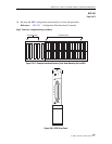
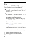
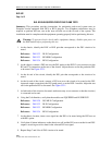
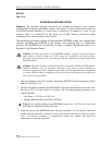
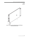
2. At the chassis, connect a DS3 test set with DS1 option to the DSX-3 cross-connect or to the
RX and TX connections at the rear of the chassis. Adjust the test set for the particular DS1
to be tested. See Figure 522-1.
3. At the far end of the circuit, identify the DS1 pair that corresponds to the circuit to be
tested.
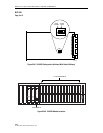
4. At the far end of the circuit, connect a DS1 test set to the circuit to be tested at the DS1
input and output connections, the DS1 patch panel, or at the DSX-1 module. Adjust the test
set for the particular DS1 to be tested. See Figure 522-1.
5. At both ends of the circuit to be tested, make necessary cross-connects so that the circuit(s)
is connected end-to-end.
6. Using the Craft Interface, verify that the modules are EQUIPPED and IN SERVICE.
Reference:
DLP-529 DS3 MUX Configuration
Reference:
DLP-532 DLX Configuration
Reference:
DLP-533 RLXIOR Configuration
Reference:
DLP-534 RLX Configuration
7. At the chassis location, insert a test signal into the DS1 to be tested using the DS3 test set
with DS1 option.
8. Verify that all alarm indicators on the chassis are off and the DS1 test set at the far end DS1
output is receiving error-free data for the selected DS1 test signal.
9. Repeat Steps 7 and 8 for all DS1 circuits to be tested.