ADCP-61-471 • Issue 4 • June 2000 • Section 2: Operation and Maintenance
2-9
© 2000, ADC Telecommunications, Inc.
NTP-002
Page 1 of 3
MODULE INSTALLATION AND TESTING PROCEDURES
Summary
: This procedure provides instructions for installing the various modules in the
installed chassis and verifying operation. Installation includes inspecting the chassis for proper
installation, checking the power supply, inserting the modules into the chassis, and testing
various functions. This procedure assumes that the Soneplex Broadband chassis and associated
Heat Baffle/Fiber Management Panel are installed in the rack, and that all power, signal, and
alarm cables are connected. This procedure must be performed before attempting to test or
operate the entire circuit or system that will be using this equipment.
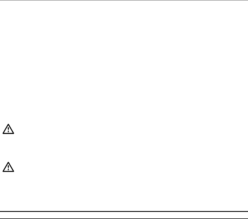
Danger:
To avoid electric shock, be careful when working near HDSL loop connections
or telecommunications circuits. An electrical potential of ±130 volts exists on HDSL
loop connections and telecommunications circuits. Coming in contact with this high
electrical potential will result in death or severe personal injury.
Caution: Electronic modules can be damaged by electrostatic discharge (ESD). Before
handling modules, wear an anti-static discharge wrist strap to prevent damage to
electronic components. Place modules in anti-static packing material when transporting
or storing. When working on modules, always place them on an approved anti-static mat
that is electrically grounded.
Do Items Below in the Order Listed For Details Go To
1. Obtain the following tools and equipment:
• #2 or #3 Phillips-head screwdriver
• Anti-static wrist strap
• Digital volt ohmmeter (VOM)
• Optical power meter (if installing ODS2 modules)
• Standard hand tools
• Two fiber optic patch cables (1 to 3 meters long each)
2. Open Soneplex Broadband chassis front cover.
3. Inspect the Soneplex Broadband chassis for proper installation and
correct installation of all cables. Refer to the Soneplex Broadband
System
Chassis Installation Manual, listed under Related
Publications at the beginning of this manual, for more information.
4. If required, unpack modules from their shipping container (they may
be stored in the chassis). Inspect for damage or missing parts. DLP-500


