


ADCP-61-471 • Issue 4 • June 2000 • Section 2: Operation and Maintenance
2-92
© 2000, ADC Telecommunications, Inc.
DLP-529
Page 1 of 4
DS3 MUX CONFIGURATION
Summary:
This procedure provides instructions for equipping each DS3 MUX as required, set
its service state, and set its protect status.
Note:
A “toggle” field type means the user can press the space bar to view and select the
next option that is described; or the user can press the “R” key to view and select the
previous option. An “input” field type means the user must type an entry in the field
according to the parameters described. A “fixed” field is locked, and cannot be changed
by the user.
Note:
Edits can be
made
in the configuration database in one of two ways: 1) If the
complete field is highlighted, use the space bar to toggle forward or the “R” key to
reverse toggle through the options for that field. 2) If only the first space or the field is
highlighted, type in the data that applies to that field.
Note:
Edits in the configuration database can be
saved
after each change in one of two
ways: 1) Press an arrow key and then Enter or Return
once
; or 2) Press Enter or Return
twice
after all selections and entries are made in the screen but before leaving the screen.
If the entries have been accepted, a message “Configuration Successful…Press Any Key
To Continue” appears on the screen.
Note:
Press CONTROL-A for help information on moving around and editing fields.
1.
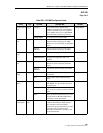
C1 or D1 DS3 MUX only:
Refer to Table 529-1 for DIP switch settings for the C1 or D1
DS3 MUX, and DS3 CAM (Communications Channel Access Module) channels. Channels
2, 5, 6, and 7 are available on both the DS3 MUX and the DS3 CAM for communication
between the central office chassis and the remote control chassis. Although the DS3 MUX
and the DS3 CAM both have the same channels, please note that their switch settings are
different.
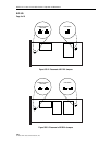
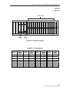
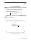
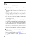
Refer to Figure 529-1 for a detailed drawing of the switch. When a C1 or D1 DS3 MUX is
used with a DS3 Soneplex Remote Control system, the DIP switches on the DS3 MUX
board must be set to the correct communications channel. To assure proper operation, the
same channel must be selected on the DS3 MUX as well as on the DS3 CAM installed in
the remote control chassis. Figure 529-2 shows the location of the switch on the DS3 MUX.
Note:
For more information on the D1 DS3 MUX, refer to the Soneplex D1 DS3 MUX
Installation Instructions manual, which is listed under Related Publications at the
beginning of this manual.
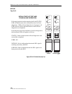
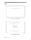
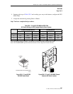
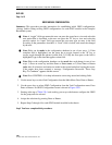
2. Use the arrow keys to select Unit Configuration from the Main Menu. Press Enter or
Return. The Unit Configuration menu appears, as shown in Figure 529-3.
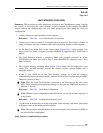
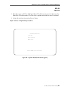
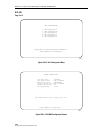
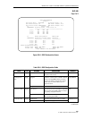
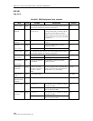
3. Use the arrow keys or number keys to select MUX Configuration from the Unit
Configuration menu. Press Enter or Return. A DS3 MUX Configuration screen is shown in
Figure 529-4.