


ADCP-61-471 • Issue 4 • June 2000 • Section 2: Operation and Maintenance
2-33
© 2000, ADC Telecommunications, Inc.
DLP-504
Page 1 of 2
LOCAL CRAFT INTERFACE CONNECTION
Summary:
This procedure provides instructions for accessing the Craft Interface. It can be
accessed locally from a VT-100 compatible terminal or a host computer connected to either the
front or rear of the Soneplex Broadband chassis.
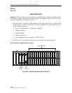
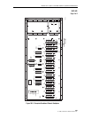
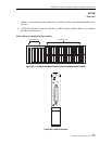
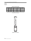
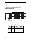
1. Locate the port that will be used to connect the control terminal or host computer to the
Craft Interface. The MPU Craft port is located on the front of the MPU as shown in Figure
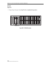
504-1 and is configured as a DCE connection. Ports 2 and 3 are located on the chassis rear
panel and are configured as DTE connections.
2. Select the cable that is required for connecting the terminal or computer to the chassis.
Maximum length of the cable is specified by the EIA-232 protocol. A straight-through, 25-
pin, connectorized EIA-232 cable is required to connect the terminal or computer to the
MPU Craft port. Pin-out information for the MPU Craft port is shown in Table 504-1. A
null-modem cable or adapter is required to connect the terminal or computer to Port 2 or
Port 3. Ports 2 and 3 provide an EIA-232 interface and use 25-pin D-subminiature female
connectors for the cable connections.
3. Connect one end of the cable to the terminal or computer and the other end to the
appropriate port.
4. Turn on the power to the terminal or computer. If using a computer, enter the
communications software package resident on the computer. Serial port default settings are
listed in Table 549-1.
Reference:
DLP-549 Serial Port Configuration
5. Press Enter or Return.
6. The Logon screen with User Name field should appear.
Stop! You have completed this procedure.