


ADCP-61-471 • Issue 4 • June 2000 • Section 2: Operation and Maintenance
2-235
© 2000, ADC Telecommunications, Inc.
DLP-573
Page 4 of 6
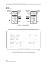
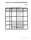
Table 573-1. HLX Loopback Configuration Fields
FIELD TYPE OPTIONS DESCRIPTION DEFAULT
Group Toggle 1, 2, 3, 4, 5, 6, or 7 Specifies the module’s group
number designated on the chassis.
Blank
Slot Toggle 1, 2, 3, or 4 Specifies the module’s slot number
designated on the chassis.
Blank
Circuit ID Input Up to 20 characters. This represents the customer’s circuit
ID. The first and last characters must
be alpha or numeric; middle
characters can be alpha, numeric, or
hyphens. Note: This field can be
configured only after the T1
Provision field (described in DLP-
531) is set to YES.
Blank
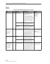
HLXC Activation
Code
(“Activation Code” is
equivalent to
“Programmable
Code.”)
Input 16 binary characters (0’s
and 1’s) must be entered.
16-bit codes can be set to any 16-bit
binary value except: all 0s, all 1s, or
a value that is already used in another
16-bit code. The signal is sent
inband. HDSL units go to loopup
state when they are in armed state.
Loopup is activated for selected
units. Detection time is 3 secs.
1101 0011 1101 0011
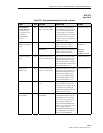
HLXC Programmable
Lpbk
Toggle ENABLED Enables response to programmable
loopback codes and overrides
hardware configuration settings.
MPU V5.1:
DISABLED
DISABLED Disables response to programmable
loopback codes and overrides
hardware configuration settings.
MPU V5.2:
ENABLED
ESF Inband Loopback
Toggle ENABLED*
Version E HLXC:
Enables ESF
inband loopback.
Version E HLXC:
ENABLED
DISABLED*
Version E HLXC:
Disables ESF
inband loopback.
Version D or earlier
HLXC
: N/A
N/A
Version D or earlier HLXC only:
this field cannot be configured.
* In order for the ESF Inband Loopback field to be configured, some HLX Unit Configuration screen fields must be configured as
follows: Unit Equip State = EQUIPPED, Unit Service State = IS, T1 Provision = YES, TI Service State = IS, and T1 Framing
Format = ESF.
(continued)