


ADCP-61-471 • Issue 4 • June 2000 • Section 2: Operation and Maintenance
2-93
© 2000, ADC Telecommunications, Inc.
DLP-529
Page 2 of 4
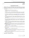
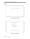
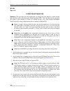
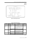
4. Starting at the top of Table 529-2 and working your way to the bottom, configure the DS3
MUX fields.
5. Assign the selections by pressing Enter or Return.
Stop! You have completed this procedure.
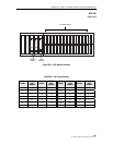
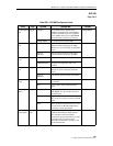
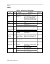
Table 529-1. C1 and D1 DS3 MUX and DS3 CAM
DIP Switch Settings for DS3 Soneplex Remote Control System
C1 AND D1 DS3 MUX SWITCH DS3 CAM SWITCH
CHANNEL 1 2 3 1 2 3
7 N/A OPEN OPEN OPEN OPEN N/A
6 N/A OPEN CLOSED OPEN CLOSED N/A
5 N/A CLOSED OPEN CLOSED OPEN N/A
2 N/A CLOSED CLOSED CLOSED CLOSED N/A
Note: The default setting is channel 7 for both the C1 and D1 DS3 MUX and the DS3 CAM.
Note: The CLOSED/OPEN position indicates that the switch is depressed in that direction.
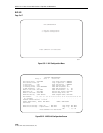
10509-A
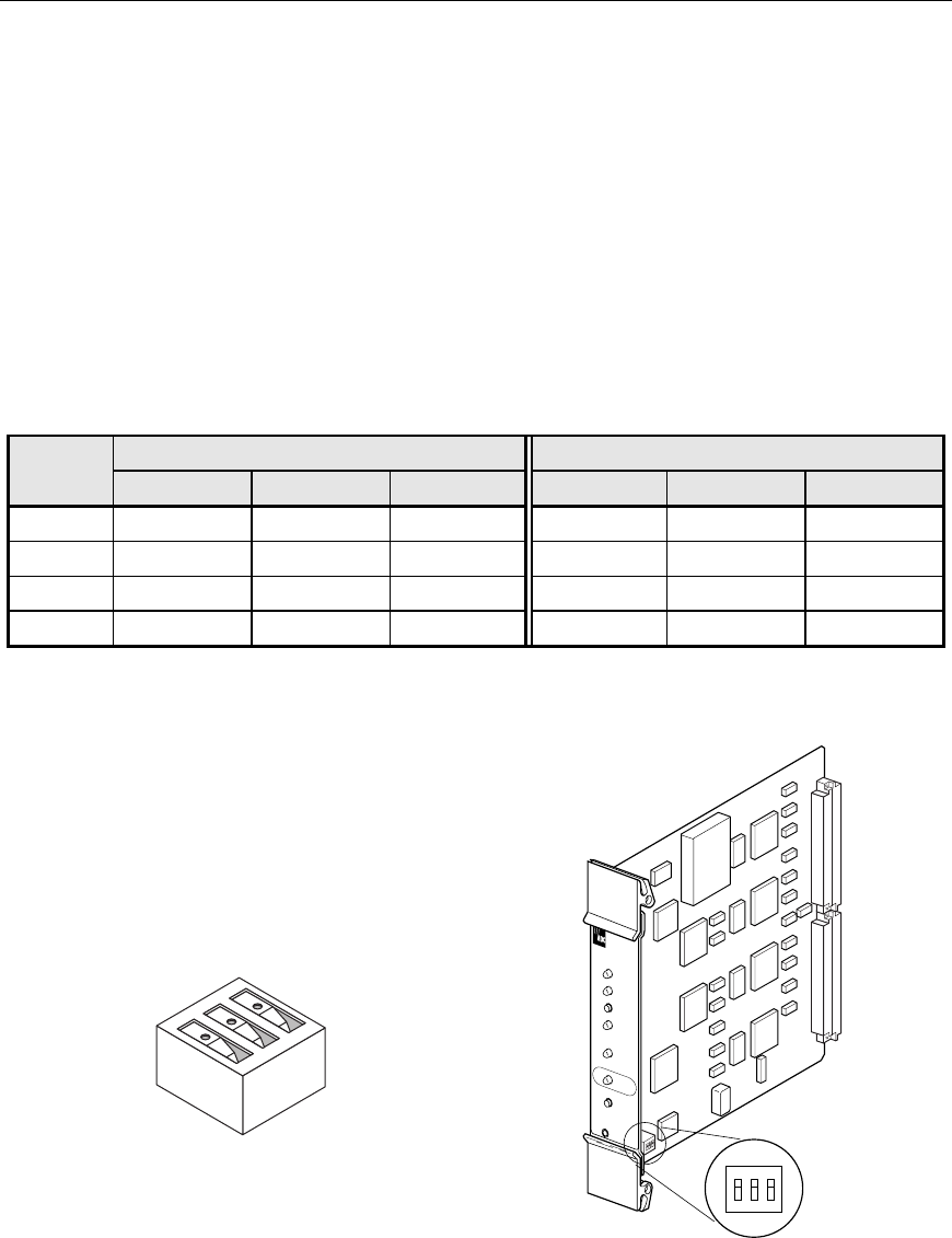
OPEN
1
2
3
CLOSED
(ON)
OPEN
(OFF)
ON OFF
All switches shown are in the OFF position.
123
OPEN
STATUS
D
S
3
M
U
X
RESET
LPBK
APS
ENABLE
ONLINE
LMPTST/
APS
DS3 FAIL
LOCKOUT
FORCE
7902-A
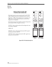
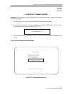
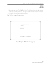
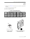
Figure 529-1. C1 and D1 DS3 Figure 529-2. C1 and D1 DS3 MUX Channel
MUX DIP Switch Detail Selection DIP Switch Location