


ADCP-61-471 • Issue 4 • June 2000 • Section 2: Operation and Maintenance
2-113
© 2000, ADC Telecommunications, Inc.
DLP-533
Page 5 of 5
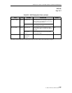
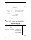
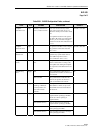
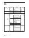
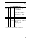
Table 533-1. RLXIOR Configuration Fields, continued
FIELD TYPE OPTIONS DESCRIPTION DEFAULT*
Loopback
Activation Code
Input 16 binary characters (0’s
and 1’s) must be entered.
These codes can be set to any 16-bit
binary value except: all 0s, all 1s, or a
value that is already used in another 16-bit
code.
The Loopback Activation Code signal is
sent inband. RLX units go to loopup state
when they are in armed state. Loopup is
activated for selected units. Detection time
is 3 secs.
1101 0011 1101 0011
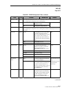
Loopback
Deactivate Code
Input The signal is sent inband. Units in loopup
state go back to armed state. Detection
time is 5 secs.
1001 0011 1001 0011
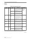
Lpbk Timeout
Disable Code
Input This disables loopup time-out. Active
loopbacks stay up until deactivation or
disarm (NID Loop Down) code is
received. Detection time is 3 secs.
1101 0101 1101 0110
Loopback Timeout
Period
Input Enter a number from 0 to
255.
This represents the minutes the loopback
remains in effect before reverting to the
non-loopback state. Setting the loopback
time out period to 0 disables the time out
feature.
0 minutes
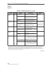
Network Keep
Alive
Toggle AIS If the system detects an LOS (Loss of
Signal) from the customer, an AIS is sent
to the network.
AIS
DS1 CUTOFF If the system detects an LOS from the
customer, the signal is cut off and no
signal is transmitted to the network.
DS0 Channel Toggle “B” (for DS0 Channel
blocking) or blank (for
normal operation) for
each of the 24 DS0
channels.
Blocking a channel causes the blocking
pattern (FFhex or 7Fhex) set up via the
onboard DIP switch to be transmitted in
both directions.
Blank
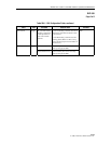
Unit Service State Toggle IS (In-Service) Places the unit in service and allows
equipment alarm reporting by the MPU.
Must be set to IS for reporting of
equipment alarms.
OOS
OOS (Out-Of-Service) Removes unit from service and stops
equipment alarm reporting by the MPU.
T1 Service State Toggle IS (In-Service) Places facility in service and allows T1
alarm reporting by the MPU.
OOS
OOS (Out-Of-Service) Removes facility from service and stops
alarm reporting by the MPU.
*Note: The RLXIOR configuration field default values shown in this manual are valid for systems with an MPU installed.