


ADCP-61-471 • Issue 4 • June 2000 • Section 2: Operation and Maintenance
2-187
© 2000, ADC Telecommunications, Inc.
DLP-558
Page 2 of 3
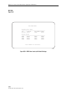
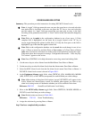
4. Repeat Step 3 for each field that you wish to change.
5. Assign the selections by pressing Enter or Return.
6. Momentarily press RESET on the MPU front panel, or perform a soft reset, in order to re-
initialize the X.25 configurations.
Reference:
DLP-519 MPU Replacement and Testing
Reference:
DLP-538 Reset/LED Test Commands
Stop! You have completed this procedure.
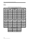
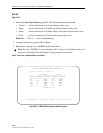
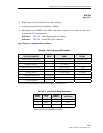
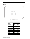
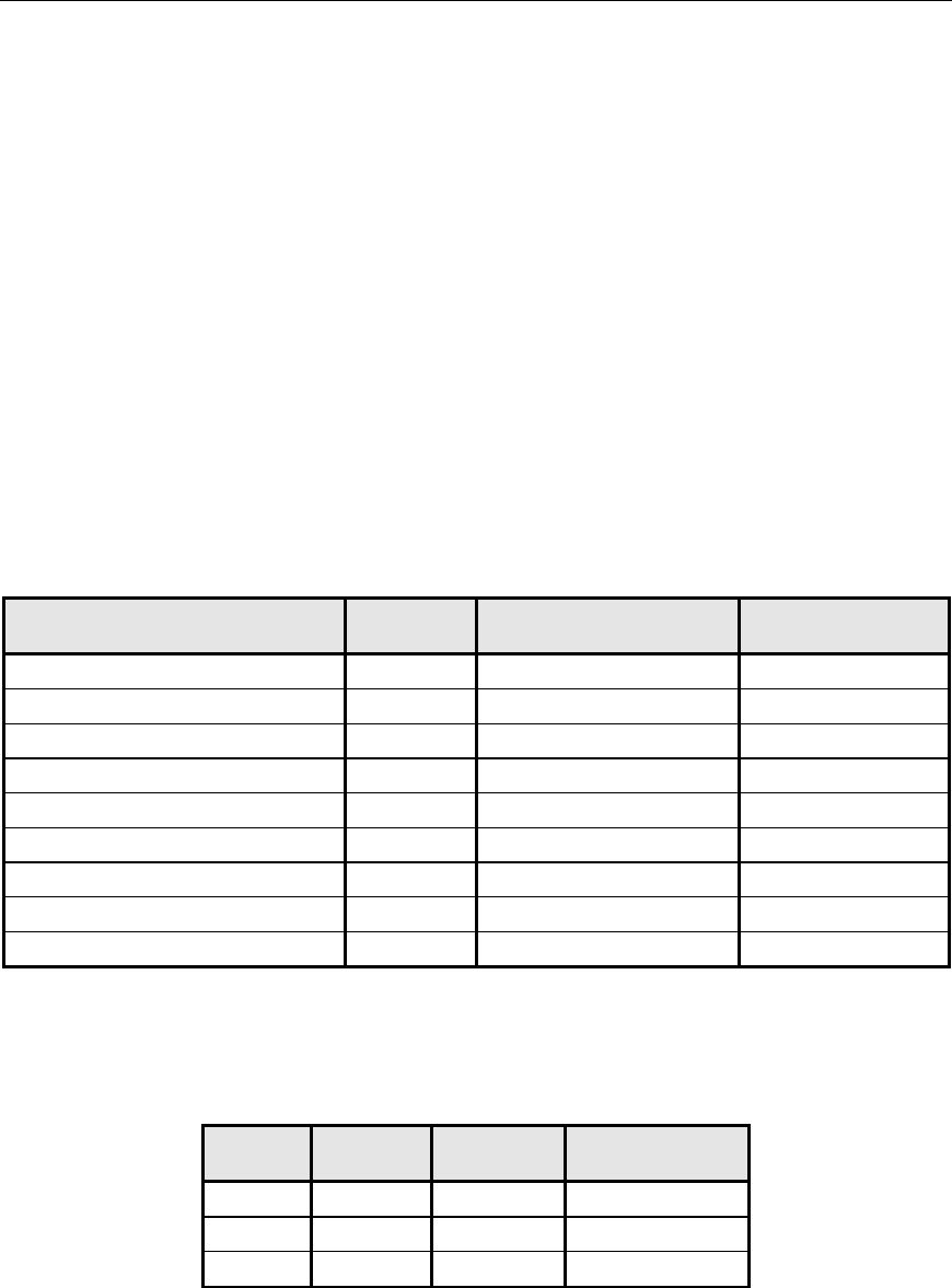
Table 558-1. Data Link Layer LAPB Parameters
DATA LINK PARAMETER
SET
VALUE RANGE
CONFIGURABLE
DEFAULT
Address Field Assignment
*
DTE, DCE (A=1, B=3) DTE (A=3, B=1)
Modulo 8
Window Size (K)
*
1 to 7 frames 7
Frame Size (Bits per I frame)
*
1080, 2104 bits 2104
N2 (retransmission count)
*
2 - 16 7
T1 (retry timer)
*
2 to 20 seconds 3 seconds
T2 (response delay timer) 0.3 seconds
T3 (not supported)
T4 (not supported)
* These are user-programmable parameters through the Craft Interface.
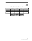
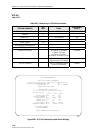
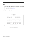
Table 558-2. Virtual Circuit Default Assignments
VIRTUAL
CIRCUIT
CIRCUIT
TYPE
LOGICAL
CHANNEL # APPLICATION
1 PVC 1 TL1
2 PVC 2 Craft
3 SVC N/A N/A
Note
: Autonomous messages are always sent except when
inhibited by the TL1 INH-MSG command.