AMD Geode™ LX Processors Data Book 287
Display Controller
33234H
6.5.1.10 Output Formats
Video Output Data Sequencing
The order that video data is transmitted from the DC to the
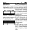
VP depends on the format of the video data. For YUV 4:2:0
mode, the entire stream of Y data is transmitted for a
source line, followed by the entire stream of U data for the
line, and finally, the entire stream of V data for the line. The
size of the U and V streams are always one-half the size of
the Y stream. The data is not interlaced as in the YUV 4:2:2
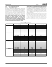
mode. The data ordering is shown in Table 6-37.
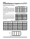
For YUV 4:2:2 mode, YUV data is interlaced in a single
stream, with a maximum size of 1440 bytes.
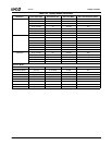
In YUV 4:2:2 mode, four orders of YUV data are supported.
The data format is selectable via the Video Configuration
register (VP Memory Offset 000h) in the Video Processor
module. The data ordering is shown in Table 6-38.
6.5.2 VBI Data
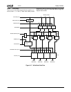
VBI (Video Blanking Interval) data is fetched by the DC at
the start of each frame. The data is fetched from a buffer in
memory, separately from video or graphics data. It is pre-
sented to the VP on the graphics port. VBI data is provided
via a path that circumvents the gamma correction palette
and the graphics filter. The data presented to the VP/VOP
is only the data in memory. There are no additional head-
ers attached by the DC. Configuration registers in the DC
determine how many lines of VBI data are sent during each
field; the lines can be enabled/disabled independently of
one another. If a line is disabled, no data is fetched (from
memory) for that line, and the memory line pointer is NOT
incremented. Thus, non-contiguous lines of screen VBI
must be stored contiguously in memory if there are no
active VBI lines between them. The DC can be pro-
grammed to fetch multiple fields worth of VBI data from lin-
ear frame buffer space without resetting to the start of the
buffer on each field. This minimizes the interrupt overhead
required to manage VBI data. VBI data streams of up to 4
KB per scan line are supported.
The VBI horizontal timings are controlled in a manner simi-
lar to the horizontal active timings. The reference point for
the horizontal (pixel) counter is the start of active video.
This means that if the VBI data is to be active before this
point on the line (i.e., to the left of, and above active video),
it may be necessary to set the VBI horizontal start point to
a large number (less than the horizontal total, but larger
than the VBI horizontal end point). The line counter used to
calculate VBI offsets is incremented at the start of each
HSYNC, and NOT at the start of active video. This means
that even if the VBI horizontal timings are such that it starts
during the horizontal “back porch” region, the line counts
and enables are the same as if the VBI horizontal timing
was the same as the graphics timing.
6.5.3 GenLock
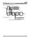
The DC has the ability to use an external source to deter-
mine the timing and frequency of VSYNC. This is primarily
used in systems in which the VIP is providing video data to
be displayed in a native screen resolution and frame rate.
The DC can also be configured to detect the loss of
VSYNC in this case, and temporarily generate its own
VSYNC pulse until the external source resumes generation
of video data and synchronization. This is accomplished
through the use of a VSYNC timeout counter. The DC can
also generate an interrupt when a loss of synchronization
is detected.
Table 6-37. YUV 4:2:0 Video Data Ordering
Sequence Data Type Max Size (Bytes)
1 Y stream 1920
2 U stream 960
3 V stream 960
Table 6-38. YUV 4:2:2 Video Data Ordering
Mode YUV Ordering (Note 1)
Note 1. U = Cb, V = Cr.
0 U Y0 V Y1
1 Y1 V Y0 U
2Y0 U Y1 V
3 Y0 V Y1 U


