AMD Geode™ LX Processors Data Book 97
CPU Core
33234H
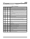
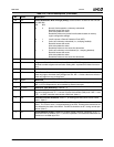
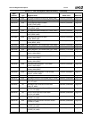
30 CD Cache Disable/Not Write-Through (Snoop). Cache behavior is based on the CR0 CD
and NW bits.
CD NW
0 0 Normal Cache operation, coherency maintained.
Read hits access the cache,
Write hits update the cache,
Read/write misses may cause line allocations based on memory
region configuration settings.
0 1 Invalid, causes a General Protection Fault (GPF).
1 0 Cache off, coherency maintained (i.e., snooping enabled).
Read hits access the cache,
Write hits update the cache,
Read/write misses do not cause line allocations.
1 1 Cache off, coherency not maintained (i.e., snooping disabled).
Read hits access the cache,
Write hits update the cache,
Read/write misses do not cause line allocations.
29 NW
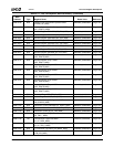
28:19 RSVD Reserved.
18 AM Alignment Check Mask. If AM = 1, the AC bit in the EFLAGS register is unmasked and
allowed to enable alignment check faults. Setting AM = 0 prevents AC faults from occur-
ring.
17 RSVD Reserved
16 WP Write Protect. Protects read only pages from supervisor write access. WP = 0 allows a
read only page to be written from privilege level 0-2. WP = 1 forces a fault on a write to a
read only page from any privilege level.
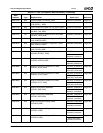
15:6 RSVD Reserved.
5NE Numerics Exception. NE = 1 to allow FPU exceptions to be handled by interrupt 16.
NE = 0 if FPU exceptions are to be handled by external interrupts.
4ET (RO) Extension Type (Read Only). (Default = 1)
3TS Task Switched. Set whenever a task switch operation is performed. Execution of a float-
ing point instruction with TS = 1 causes a Device Not Available (DNA) fault. If MP = 1 and
TS = 1, a WAIT instruction also causes a DNA fault. (Note 1)
2EM Emulate Processor Extension. If EM = 1, all floating point instructions cause a DNA
fault 7. (Note 1)
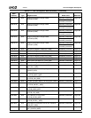
1MP Monitor Processor Extension. If MP = 1 and TS = 1, a WAIT instruction causes DNA
fault 7. The TS bit is set to 1 on task switches by the CPU. Floating point instructions are
not affected by the state of the MP bit. The MP bit should be set to 1 during normal oper-
ations. (Note 1)
0PE Protected Mode Enable. Enables the segment based protection mechanism. If PE = 1,
protected mode is enabled. If PE = 0, the CPU operates in real mode and addresses are
formed as in an 8086-style CPU.
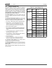
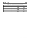
Note 1. For effects of various combinations of the TS, EM, and MP bits, see Table 5-11 on page 98.
Table 5-10. CR0 Bit Descriptions (Continued)
Bit Name Description


