AMD Geode™ LX Processors Data Book 401
Video Processor
33234H
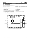
6.7.6.4 Interface to Video Processor
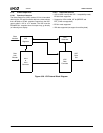
The output from the Video Processor is connected via a
24-bit bus. Bytes on this bus are aligned as shown below:
[23:16] Y
[15:8] Cr (V)
[7:0] Cb (U)
The VOP takes this 24-bit 4:4:4 data bus and converts it to
a 16-bit 4:2:2 data bus (the Y component on the high byte,
the U/V components alternating on the low byte).
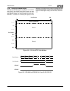
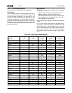
The VOP provides three different methods for translating
from 4:4:4 to 4:2:2 data depending on the value of the
mode select bits from the VOP Configuration register (VP
Memory Offset 800h[5:4]) as shown in Table 6-61.
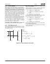
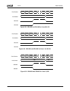
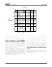
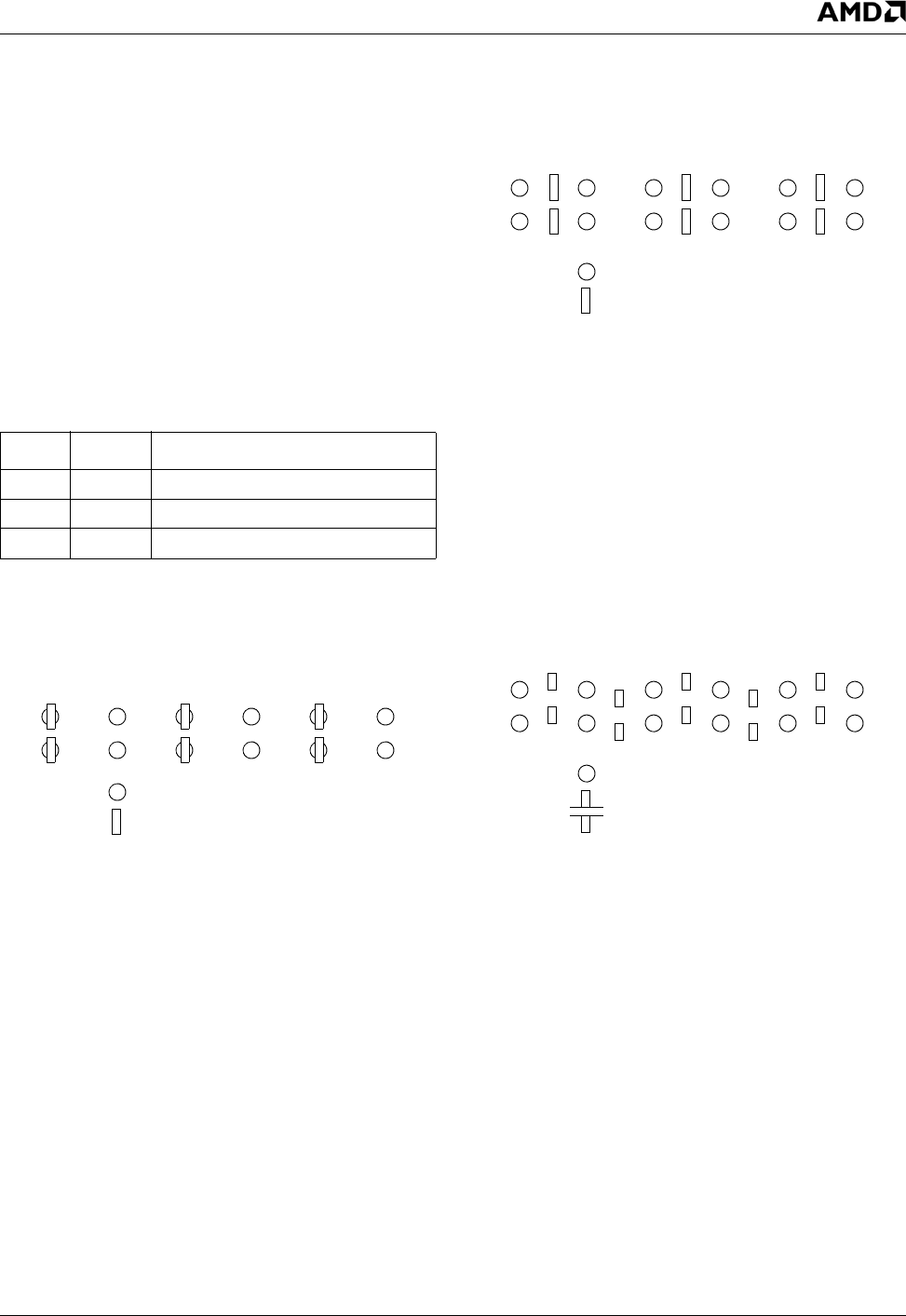
Mode 0: 4:2:2 Co-sited
In this mode, the U/V samples are dropped on alternating
sample sets, resulting in the below representation.
Sampling algorithm:
Y, U, V : 4:4:4 Input data
Y’, U’, V’ : 4:2:2 Sampled data
Y1’ = Y1, U1’ = U1, V1’ = V1
Y2’ = Y2
Y3’ = Y3, U3’ = U3, V3’ = V3
etc.
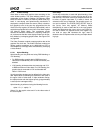
Mode 1: 4:2:2 Interspersed
In this mode, adjacent pairs of U/V sample data are aver-
aged, with the U/V samples coming from the same adja-
cent sample sets.
Sampling algorithm:
Y, U, V : 4:4:4 Input data
Y’, U’, V’ : 4:2:2 Sampled data
Y1’ = Y1, U1’ = (U1+U2)/2, V1’ = (V1+V2)/2
Y2’ = Y2
Y3’ = Y3, U3’ = (U3+U4)/2, V3’ = (V3+V4)/2
etc.
Mode 2: 4:2:2 Interspersed (free-running)
This mode is the same as Mode 1 with the exception that
the U sample is averaged between the first two samples,
and the V sample is averaged between the second and
third samples.
Sampling algorithm:
Y, U, V : 4:4:4 Input data
Y’, U’, V’ : 4:2:2 Sampled data
Y1’ = Y1, U1’ = (U1+U2)/2
Y2’ = Y2, V2’ = (V2+V3)/2
Y3’ = Y3, U3’ = (U3+U4)/2
Y4’ = Y4, V3’ = (V4+V5)/2
etc.
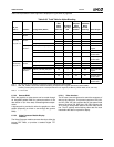
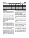
Table 6-61. VOP Mode
Mode Bits Description
000
4:2:2 Co-sited (Recommended)
101
4:2:2 Interspersed
210
4:2:2 Interspersed, free-running
Luminance (Y) Samples
Chromance (U,V) Samples
Luminance (Y) Samples
Chromance (U,V) Samples
Luminance (Y) Samples
Chromance (U) Samples
Chromance (V) Samples


