Cable, Port, and Pinout Information 47
Serial Cable Connection
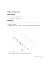
You can use serial cables (null-modem) to connect the switch to a terminal for initial setup and
configuration (You can also use a PC running terminal emulation software.). The switch’s serial
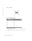
cable is female to female DB-9 crossover cable (see Figure 3-3).
Figure 3-3 shows the serial cable and Table 3-3 shows the serial connector pin assignments.
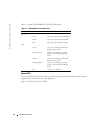
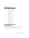
6 Module definition 0; grounded within the
module
7 Rate select; no connection required.
8 Loss of signal indication; logic 0 indicates
normal operation.
9 Receiver ground (common with
transmitter ground)
10 Receiver ground (common with
transmitter ground)
11 Receiver ground (common with
transmitter ground)
12 Receiver inverted data out; AC coupled.
13 Receiver non-inverted data out; AC
coupled.
14 Receiver ground (common with
transmitter ground)
15 Receiver power supply
16 Transmitter power supply
17 Transmitter ground (common with
receiver ground)
18 Transmitter non-inverted data in
19 Transmitter inverted data in
20 Transmitter ground (common with
receiver ground).
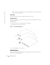
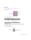
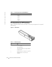
Table 3-2. SFP Pin Connections
Pin Use


