424 Configuring Quality of Service
www.dell.com | support.dell.com
NOTE: The DSCP values 3, 11, 19, 27, 35, 43, 51, and 59 are mapped to q1, q2 ... q8. These settings cannot
be changed.
•
Layer 4 Predefined Fields
—Configures the system to use the TCP/UDP destination port of
the incoming packet to map the packet to the output priority queues. The mapping of the
TCP/UDP destination port to a priority queue is set on a per system basis, in two separate
tables. It can be
enabled
or
disabled
per port.
•
None
—All traffic is classified to the best effort service.
After packets are assigned to a specific queue, using the chosen classification method various
services can be applied. Scheduling for output queues can be configured, including:
• Strict priority.
• Weighted Round Robin (WRR)
• A combination of these methods.
Scheduling schemes are specified per system. WRR weights to the queues can be assigned in any
order. The weight settings are available on a per port basis.
For each interface or queue, the following output shaping can also be configured:
• Burst size.
• Committed Information Rate (CIR).
• Actions for over-the-limit traffic.
QoS Modes
QoS is enabled in the PowerConnect 6024/6024F in either basic or advanced QoS mode.
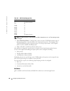
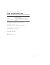
Table 10-2. DSCP Default Mapping Table
DSCP Value Queue Number
0-7 q1 (Lowest Priority)
8-15 q2
16-23 q3
24-31 q4
32-39 q5
40-47 q6
48-55 q7
55-63 q8 (Highest Priority)


