


7
Series 90–70 Remote I/O Scanner User’s Manual – July 1992108
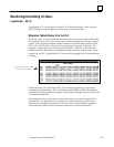
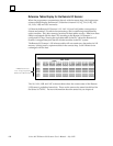
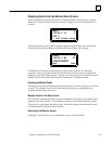
Reference Tables Display for the Remote I/O Scanner
When the programmer communicates directly with the remote drop, the Logicmaster
reference tables display the Remote I/O Scanner’s internal %I, %Q, %AI, %AQ, %R,
%S, %SA, %SB, and %SC memories.
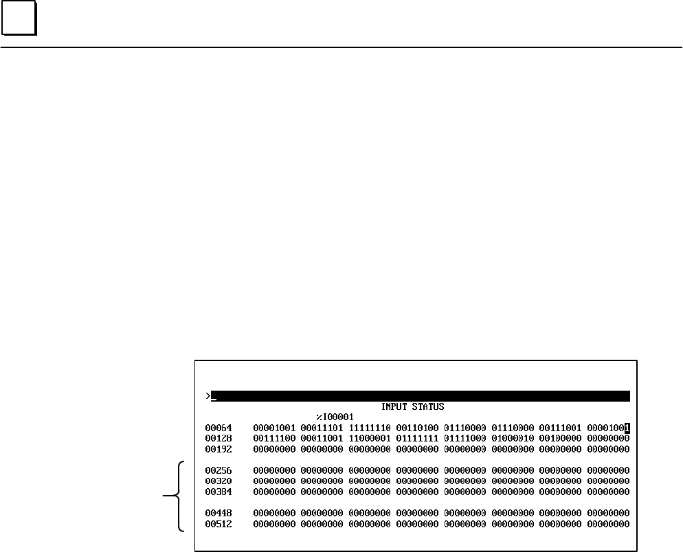
I/O data in the Remote I/O Scanner’s %I, %AI. %Q, and %AQ tables corresponds to
discrete and analog I/O cards in the remote drop, and/or data being manipulated by
option modules. Any other memory locations in these tables are zero. Data from these
tables is exchanged with the host CPU according to the Remote I/O Scanner’s
configured I/O map. Viewing the equivalent table in the PLC shows the Remote I/O
Scanner’s mapped data plus data for all other modules in the PLC system.
The Remote I/O Scanner’s %R reference table will not contain any data unless its %R
memory is being used by option modules in the remote drop. Such %R data is not
exchanged with the host.
PLC references
not displayed at
Remote I/O Scanner
The %S, %SA, %SB, and %SC reference tables show the current states of the Remote
I/O Scanner’s predefined status bits. These are the same as the status bits defined for
the Series 90–70 PLC. For more information about the status bits, see chapter 8.