


2
Series 90–70 Remote I/O Scanner User’s Manual – July 199230
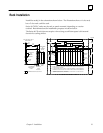
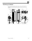
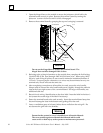
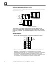
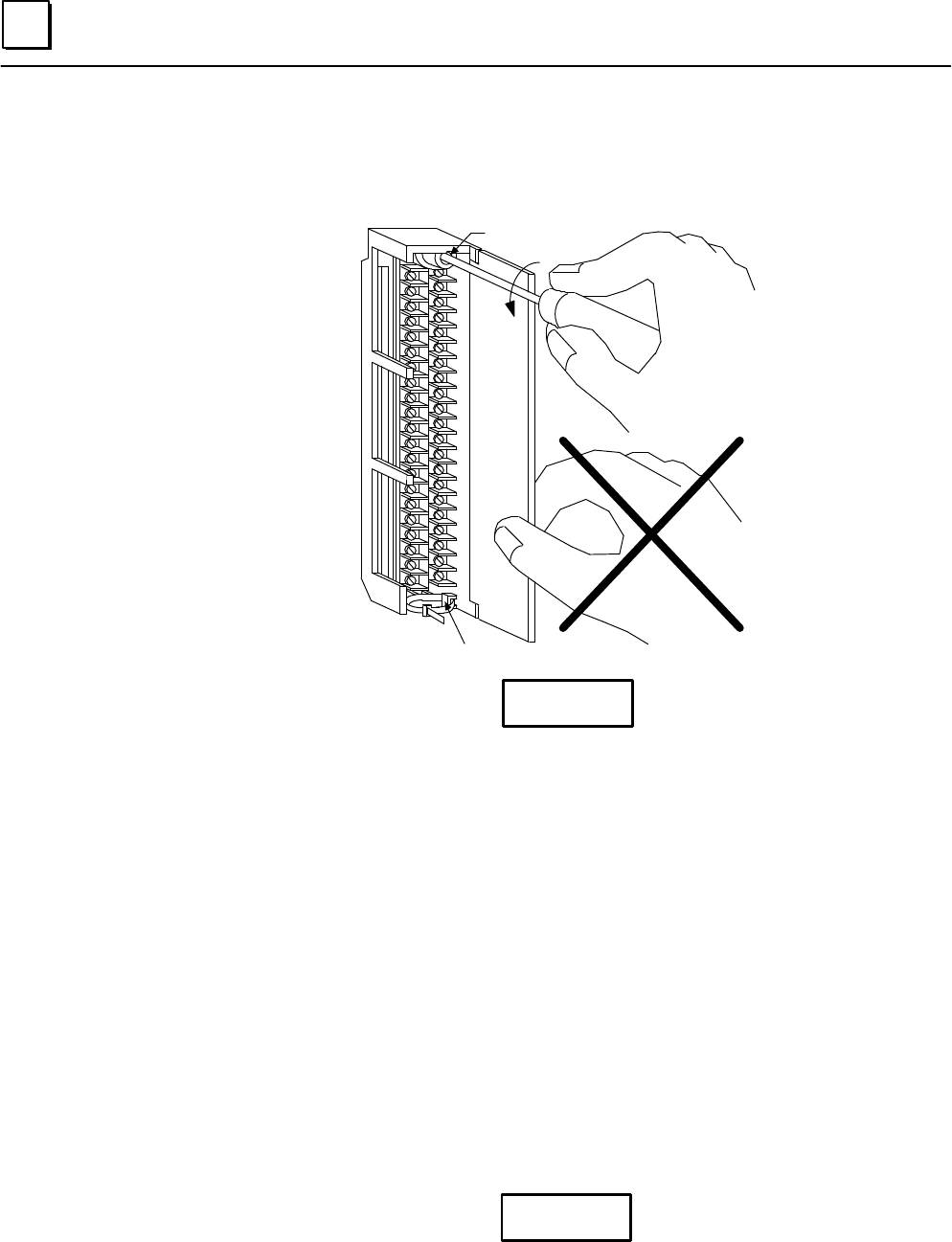
1. Open the hinged door on the module to access the jackscrew which holds the
terminal board securely in place. Remove the terminal board by turning the
jackscrew counter–clockwise until it is fully disengaged.
2. Remove the terminal board by grasping the top and swinging it outward.
a43747
JACKSCREW
WIRE BUNDLE CABLE TIE CLEAT
DO NOT
PULL
ON DOOR
Caution
Do not use the hinged door to remove the terminal board. The
hinged door could be damaged if this is done.
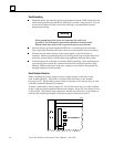
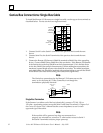
3. Referring to the wiring information on the module door, complete the field wiring.
Use AWG #22 (0.324 mm) through AWG #14 (2.08 mm) wire. When using AWG
#14 wire and wiring all points, do not exceed a maximum insulation diameter of
.135 inch. To ensure proper connection, two wires may be terminated on any one
terminal only if both wires are the same size.
4. After completing connections to all modules in a rack, secure the wire bundle.
Wrap a cable tie around the wire bundle and secure it tightly through the cable tie
cleat at the lower right corner of the terminal board. For large wire bundles, use
additional cable ties.
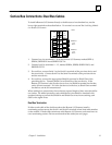
5. Record circuit wiring identification on the door label. Insert the label in the door’s
slot (crease the scored edge of the label if necessary).
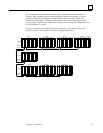
6. Fasten the terminal board to the rack securely. Insert the terminal board strap into
the small rectangular slots in the bottom card guide grill on the rack.
7. Leave a ventilation space of at least 6 inches above and below the rack grill. Do
not obstruct the grill with wire bundles.
Warning
Ensure that the protective cover is installed over all terminal boards.
The cover protects against accidental shock hazard which could
cause severe or fatal injury to the operator or maintenance personnel.