


D
149Appendix D Logicmaster 90–70, Release 3: Remote Drop Configuration Instructions
Conversely, it is possible that a PCM, GDS, or ADS module contains data which it
wishes to pass to the host, or that it requires data to be supplied by the host. To pass
data to the host, some %I or %AI memory which is not used by I/O modules must be
included in the remote drop I/O map; the PCM, GDS or ADS will then be able to
deposit data there, and that data will automatically be transported to the host. To
receive data from the host, allocate some %Q or %AQ references within the remote
drop I/O map.
Configuration Limits
There are two configuration limits that must not be exceeded:
There must not be too many option modules in the remote drop. This is explained
in chapter 1.
The I/O configuration data must not be greater than 4500 bytes total. This amount
of configuration data will never be reached in a remote drop where all of the I/O
modules are included in the Remote I/O Scanner’s I/O map. Turn to appendix B if
the remote drop drop will have I/O modules configured outside the I/O map, and
controlled by option modules in the remote drop.
Note
If you store (as described in Step 4) a configuration which has too
many option modules, or which contains too much I/O configuration
data, the Remote I/O Scanner will generate an “Illegal Configuration”
error message. If there was an earlier configuration previously stored
to the Remote I/O Scanner, it will be DELETED, except for the Device
Number, baud rate, and the remote drop ID.
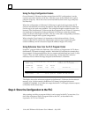
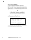
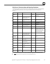
Reference View from a Remote Drop
From the remote drop, Reference View shows the references assigned to each module,
by memory type.
____ D I S C R E T E I N P U T ( % I ) V I E W ______
TOTAL I+Q: 352 HIGHEST REF CONFIGURED: 160
REFERENCE PHYSICAL IO MODULE
START – END ADDRESS TYPE TYPE DESCRIPTION
___________ _________ ______ ________ __________________________
00001–00016 0.2 90–70 I AC 16 INPUT 120 VAC 16PT ISOLATED
00017–00032 0.3 90–70 I AC 16 INPUT 120 VAC 16PT ISOLATED
00033–00064 0.4 90–70 I DC 32 INPUT 24 VDC 32PT
00065–00096 0.5 90–70 I DC 32 INPUT TTL 32PT
# 00097–00128 0.6 90–70 I DC 32 INPUT 12VDC 32PT POS/NEG LOGIC
In this example, the Remote I/O Scanner is assigned references %I00001 to %I00097. It
is within this range that the PLC will accept inputs from modules in the remote drop.
However, as the configuration display shows, one input module in the remote drop
has been assigned references above %I00097. Any # characters in the left of the screen
indicate I/O references which are outside the range configured for data transfer with
the PCU. This may be done deliberately in certain applications.