


1
5Chapter 1 Introduction
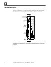
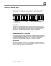
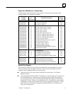
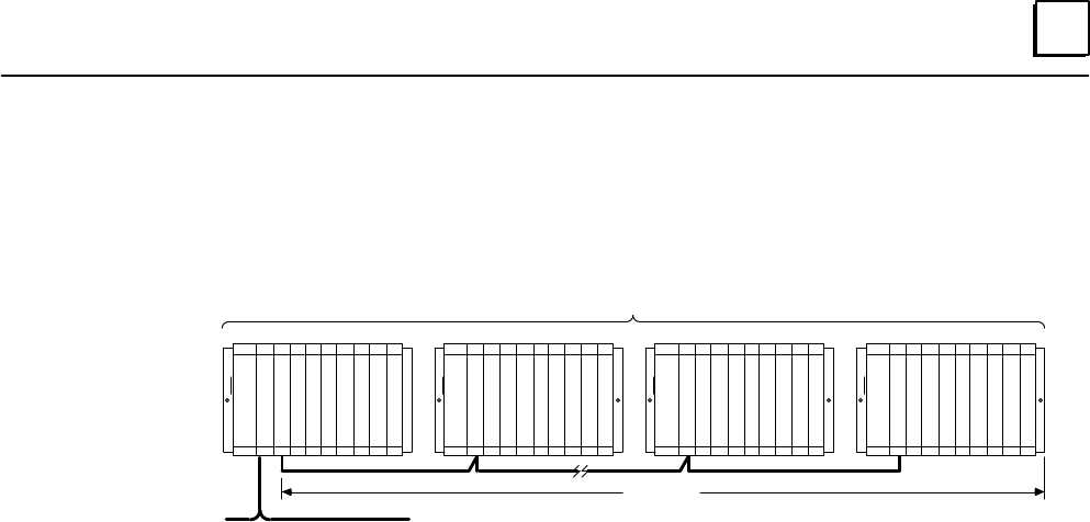
Parts of a Remote Drop
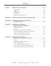
Together, a Remote I/O Scanner and the modules it serves make up a remote drop on
the Genius bus. The remote drop may consist of one to eight Series 90–70 racks.
P
S
GENIUS BUS
ALL RACKS MUST BE AT THE SAME GROUND POTENTIAL
RACK 7
P
S
B
R
M
a44875
NOTE:
P
S
A
S
C
N
N
E
R
RACK 1
B
R
M
B
T
M
RACK 6
P
S
B
R
M
UP TO 50 FEET
REMOTE DROP
RACK 0
Multiple Racks
When there are multiple racks, the Remote I/O Scanner must be located in the first
rack (rack 0). To link multiple racks in a remote drop, a Bus Transmitter (IC697BEM713)
Module in rack 0 is connected to a Bus Receiver Module (IC697BEM711) in the first
expansion rack. Additional racks are also linked via Bus Receiver Modules.
All racks in a remote drop must be at the same ground potential.
Distance Between Racks in a Remote Drop
The maximum total cable length from the first Bus Transmitter to the last Bus Receiver
in a remote drop is 50 feet (15 meters). Since none of the daisy–chained signals (all at
the same ground potential) are broken at a rack, any rack can be independently
powered–down without affecting the operation of the rest of the system.
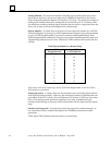
Data Quantities
Regardless of the number of racks used for a remote drop, the maximum amount of
data for a remote drop is 128 bytes of inputs and 128 bytes of outputs (8 discrete points
represent one byte and 1 analog channel uses 2 bytes).