Diagnostics
130
1606218 02 08/2006
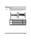
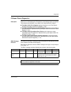
Behavior in the Event of Short-circuit / Overload / Under-voltage
Power Supply for
Splitter Boxes
and Sensors
Short-circuit / overload
The following consequences on the FTB splitter box occur when the sensor power
supply experiences a short-circuit or overload:
The diagnostics LED on the corresponding M12 connector lights up red,
corresponding diagnostics data is transmitted to the master via the bus,
all other inputs and outputs will continue to operate correctly.
Disconnecting the M12 connector of the faulty channel results in LED and
diagnostics data re-initialization.
Under-voltage / no voltage
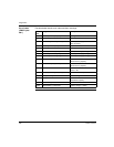
There are three under-voltage detection levels:
12 VDC ≤ U < 18 VDC: in this case, the splitter box still operates, however:
the DI-POWER LED is red,
appropriate diagnostics data is sent to the master via the bus
7 VDC ≤ U < 12 VDC: in this case, the I/Os no longer operate, however bus
communication remains operational:
the DI-POWER LED is switched off,
the relevant diagnostics data is sent to the master via the bus.
U < 7 VDC : in this case, the splitter no longer operates.
Actuators Short-circuit / overload
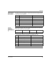
The following consequences on the FTB splitter box occur when an output
experiences a short-circuit or overload:
The diagnostics LED on the corresponding M12 connector lights up red,
the output status LED lights up red.
the corresponding diagnostics data is transmitted to the master via the bus.
To be re-activated, a default output must be set to 0 after clearing the error.
Under-voltage / no voltage
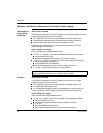
There are two under-voltage detection levels:
12 VDC ≤ U < 18 VDC: in this case, the splitter box still operates, however:
the DO-POWER LED is red,
the relevant diagnostics data is sent to the master via the bus.
U < 12 VDC:
the DO-POWER LED switches off,
the relevant diagnostics data is sent to the master via the bus.
Note: Power supply to the sensor and the Advantys FTB splitter box is provided by
the M12 connectors between pins 1 (+24 VDC) and 3 (0 VDC).


