


CANopen Network Interface
1606218 02 08/2006 39
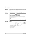
Topology
Architecture The CANopen network architecture must comply with the following limitations:
bus length / transmission speed (See Transmission Speed, p. 42),
number of connected devices (See Number of Connected Devices, p. 41),
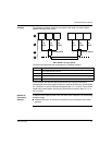
length of the taps and the space between two taps (See Tap Length, p. 40),
line terminator (See Line Terminator Resistance, p. 43).
The connections to the CANopen bus may be of the chaining or tap type.
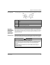
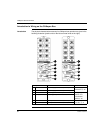
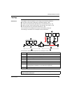
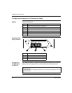
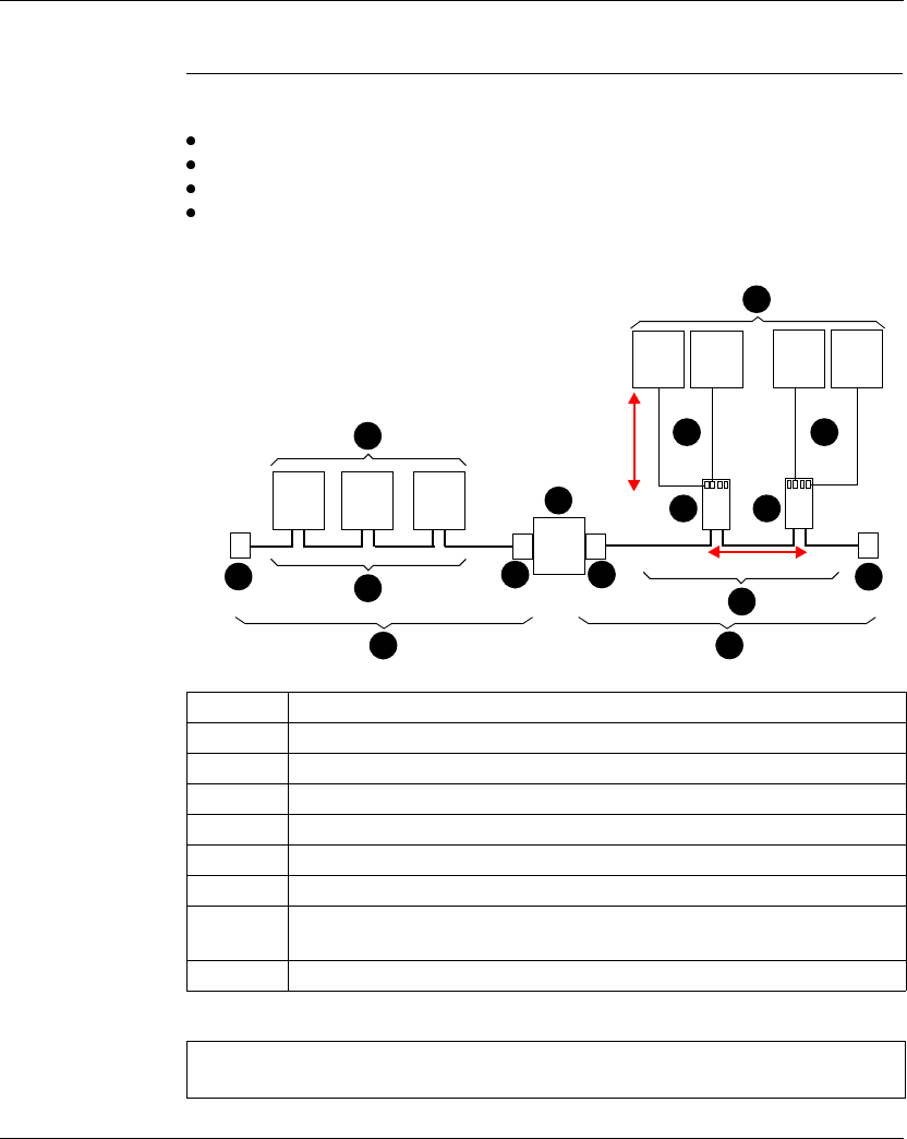
The following is an illustration of a CANopen network architecture:
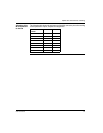
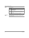
The table below describes the components of a CANopen network:
Number Description
1 CANopen devices connected by chaining
2 CANopen devices connected by tap
3 Drop cables (tap junction box / device)
4 Tap junction boxes
5 Chaining cables
6 Line terminator
7 Repeater (identical arbitration on the different bus segments)
or Bridge (different arbitration on the different bus segments)
8 CANopen bus segment
Note: A single line architecture is recommended to reduce signal reflection. Avoid
using star-type architecture.
1
2
4 4
3
6
5
6
5
3
Lmax
Min. interval
6 6
7
8
8