


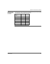

Splitter Box Characteristics and Wiring
30
1606218 02 08/2006
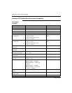
Connecting the Actuators and Sensors
Description The actuators and sensors are connected to the FTB splitter box using M12-type
connectors.
Characteristics
of the
Connections
The maximum admissible load for the FTB splitter boxes is limited to:
1.6 A per output (actuator current),
200 mA for both inputs (sensor current).
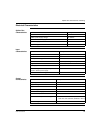
Assignment of
M12 Connector
Pins
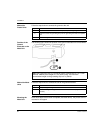
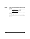
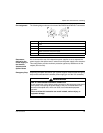
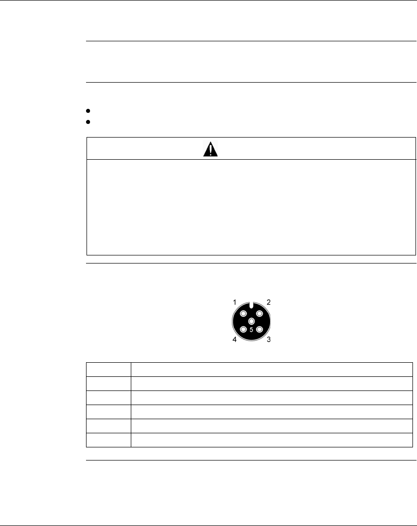
The following diagram shows the front view of a 5-pin M12 connector and the
convention for numbering the pins:
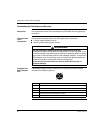
RISK OF EQUIPMENT DAMAGE AND NON-COMPLIANCE WITH IP67
Unused M12 connectors must not be left unprotected. If an M12 connector is not
correctly connected to the end of another connector or standard cable, fit a sealing
plug in order to ensure that the product is IP67 standard compliant. To ensure the
IP67 protection index, check that the cover is screwed onto the base splitter box
and that all connectors are fitted with cables or sealing plugs.
Failure to follow this instruction can result in death, serious injury, or
equipment damage.
WARNING
Pin Assignment
1 +24 VDC
2 Channel 10 to 17: diagnostics input or functional input or output
30 VDC
4 Channel 00 to 07: functional input or output
5 Ground