


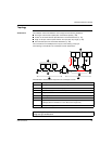
Splitter Box Characteristics and Wiring
1606218 02 08/2006 33
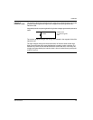
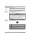
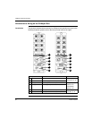
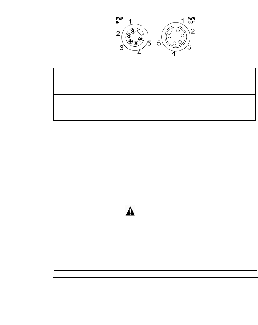
Pin Assignment The following diagram shows a front view of the PWR IN and PWR OUT connectors:
Recommen-
dations for the
Power Supply to
the Sensors,
Actuators and
Splitter Boxes
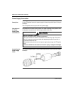
We recommend the use of 2 independent power supplies so as to separate the
power supply to the splitter boxes / sensors from the power supply to the actuators.
This configuration provides maximum protection against any disturbance on the
outputs (short circuits).
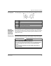
Emergency Stop Separating the splitter box/sensor (pin 4) power supplies means that the emergency
stop can be connected to the actuator power supply (pin 5 of the 7/8" connector).
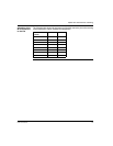
Pin Assignment
10 VDC
20 VDC
3Ground
4 Splitter box sensor and power supply
5 Actuator power supply
RISK OF UNINTENDED EQUIPMENT OPERATION
Do not connect pin 4 of the power supply connector to the emergency stop circuit
of the system. Interrupting the power supply to this pin, will deactivate the I/O
channels of the splitter box, which can result in an unintended equipment
operation.
Failure to follow this instruction can result in death, serious injury, or
equipment damage.
WARNING