


CANopen Network Interface
44
1606218 02 08/2006
Connecting the Field Bus
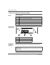
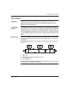
Description The splitter box can either be in the middle of the chain connection or at line end.
The field bus is connected via a 5-pin M12 connector.
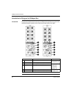
Illustration of the
Connection
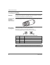
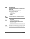
Cable Connector
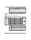
The following diagram shows the characteristics of the connection cable connector:
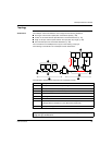
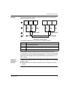
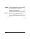
Bus Connector
Pin Assignment
The BUS IN connector is a 5-pin M12 male connector.
The BUS OUT connector is a 5-pin M12 female connector.
The following diagram shows a front view of the bus connectors:
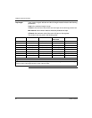
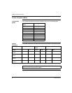
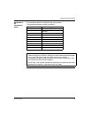
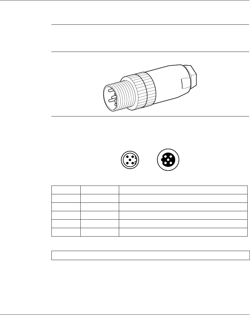
The following table gives the assignments of the bus connector pins:
Pin Signal Meaning
1 (CAN_SHLD) Optional CAN shielding
2 (CAN_V+) NC (not connected)
3 CAN_GND 0 V
4 CAN_H CAN_H bus line
5 CAN_L CAN_L bus line
Note: Pin 1 is connected to the ground connection terminal of the splitter box.
32
14
5
BUS
OUT
32
14
5
BUS
IN