


9.9ClockandOscillatorControl
9.10SystemControlRegisterDescriptions
www.ti.com
ClockandOscillatorControl
Theauxiliary(24MHz)oscillatorandtheclocksourceoftheCLKOUT,AUDIO_CLK0,andAUDIO_CLK1
outputsarecontrolledbytheclockandoscillatorcontrolregister(CLKCTL).Seethedevice-specificdata
manualfordetailsonCLKCTL.
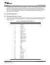
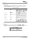
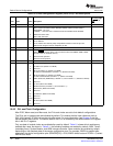
Table9-3liststhememory-mappedregistersforthesystemcontrol.Seethedevice-specificdatamanual
forthememoryaddressoftheseregistersandcompletedescriptions.
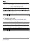
Table9-3.SystemControlRegisters
OffsetAcronymRegisterDescription
0hPINMUX0PinMultiplexingControl0
4hPINMUX1PinMultiplexingControl1
8hDSPBOOTADDRDSPBootAddress.Decodedbybootloadersoftwareforhostboots.
ChSUSPSRCEmulatorSuspendSource
10hBOOTSTATBootStatus
14hBOOTCFGDeviceBootConfiguration
24hARMBOOTARM926BootControl
28hJTAGIDDeviceIDNumber
30hHPICTLHPIControl
34hUSBCTLUSBControl
38hVIDCLKCTLVideoClockControl
3ChMSTPRI0BusMasterPriorityControl0
40hMSTPRI1BusMasterPriorityControl1
44hMSTPRI2BusMasterPriorityControl2
48hVDD3P3V_PWDNV
DD
3.3-VI/OPowerdownControl
50hTSIFCTLTSIFControl
54hPWMCTLPWMControl
58hEDMATCCFGEDMATCConfiguration
5ChCLKCTLOscillatorandOutputClockControl
60hDSPINTARMtoDSPInterruptStatus
64hDSPINTSETARMtoDSPInterruptSet
68hDSPINTCLRARMtoDSPInterruptClear
6ChVSCLKDISVideoandTSIFClockDisable
70hARMINTDSPtoARMInterruptStatus
74hARMINTSETDSPtoARMInterruptSet
78hARMINTCLRDSPtoARMInterruptClear
7ChARMWAITARMMemoryWaitStateControl
SPRUEP9A–May2008SystemControlModule109
SubmitDocumentationFeedback