


1.1Overview
1.2ARMSubsysteminTMS320DM646xDMSoC
JTAG Interface
System Control
PLLs/Clock
Generator
Input
Clock(s)
Power/Sleep
Controller
Pin
Multiplexing
ARM Subsystem
ARM926EJ-S CPU
16 KB
I-Cache
32 KB RAM
8 KB
D-Cache
8 KB ROM
DSP Subsystem
C64x+t DSP CPU
32 KB
L1 Pgm
128 KB L2 RAM
32 KB
L1 Data
High Definition
Video-Imaging
Coprocessor
(HDVICP0)
Switched Central Resource (SCR)
Peripherals
EDMA I
2
C SPI
UART
Serial Interfaces
DDR2
Mem Ctlr
(16b/32b)
Async EMIF/
NAND/
SmartMedia
ATA
Program/Data Storage
Watchdog
Timer
PWM
System
General-
Purpose
Timer
USB 2.0
PHY
VLYNQ
EMAC
With
MDIO
Connectivity
HPI
McASP
Video
Port I/F
PCI
(33 MHz)
TSIF
High Definition
Video-Imaging
Coprocessor
(HDVICP1)
CRGEN VDCE
Overview
www.ti.com
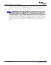
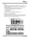
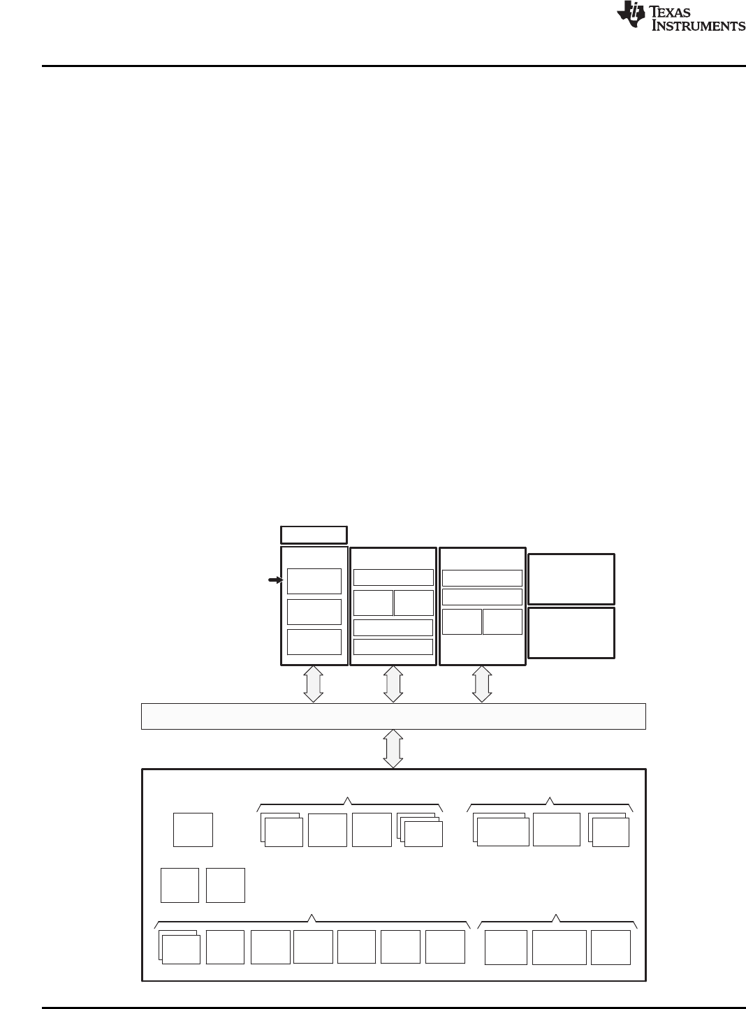
TheTMS320DM646xDigitalMediaSystem-on-Chip(DMSoC)containstwoprimaryCPUcores:1)an
ARMRISCCPUforgeneralpurposeprocessingandsystemscontroland2)apowerfulDSPtoefficiently
handleimage,video,andaudioprocessingtasks.TheDMSoCconsistsofthefollowingprimary
componentsandsub-systems:
•ARMSubsystem(ARMSS),includingtheARM926RISCCPUcoreandassociatedmemories
•DSPSubsystem(DSPSS),includingtheC64x+DSPandassociatedmemories
•TwoprogrammableHigh-DefinitionVideoImageCoprocessors(HDVICP):
•VideoDataConversionEngine(VDCE)
•VideoPortInterface(VPIF)
•AsetofI/Operipherals
•ApowerfulDMASubsystemandDDR2memorycontrollerinterface
Anexampleblockdiagram(fortheTMS320DM6467DMSoC)isshowninFigure1-1.
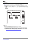
TheARM926EJ32-bitRISCprocessorintheARMSSactsastheoverallsystemcontroller.TheARM
CPUperformsgeneralsystemcontroltasks,suchassysteminitialization,configuration,power
management,userinterface,andusercommandimplementation.Chapter2describestheARMSS
componentsandsystemcontrolfunctionsthattheARMcoreperforms.
Figure1-1.TMS320DM6467DMSoCBlockDiagram
14IntroductionSPRUEP9A–May2008
SubmitDocumentationFeedback