


5.2PLL1Control
PLLDIV1(/1Prog)
PLLDIV2(/2Prog)
PLLDIV3(/4Prog)
PLLDIV4(/6Prog)
PLLDIV5(/8Prog)
PLLDIV6(/8Prog)
PLLDIV8(/8Prog)
PLLDIV9(/6Prog)
BPDIV(/1Prog)
SYSCLK1
SYSCLK2
SYSCLK3
SYSCLK4
SYSCLK5
SYSCLK6
SYSCLK8
SYSCLK9
SYSCLKBP
AUXCLK
1
0
PLLEN
PLL
1
0
CLKMODE
PLLM
CLKIN
OSCIN
PLLOUT
PLL1Control
www.ti.com
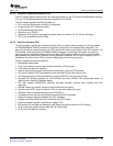
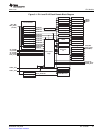
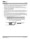
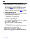
PLL1suppliestheprimaryDM646xDMSoCsystemclock.SoftwarecontrolsthePLL1operationthrough
thesystemPLLcontroller1(PLLC1)registers(baseaddress:1C40800h).Figure5-2showsthe
customizationofPLL1intheDM646xDMSoC.
•TheSYSCLKdividersareprogrammable(seeTable5-1).
•AUXCLKistheclockprovidedtothefixedclockdomains
ThePLL1multiplieriscontrolledbythePLLMbitinthePLLmultipliercontrolregister(PLLM)andissetto
adefaultvalueof15hatpower-up,resultinginaPLLmultiplierof22×.Thisdefaultsettingyieldsa
594-MHZPLLoutputclockwhenusinga27-MHZclocksource.ThePLL1multipliermaybemodifiedby
software(forexample,setto18×fora486-MHZoperation).
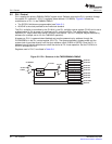
Atpower-up,PLL1ispowered-down/disabledandmustbepowered-upbysoftwarethroughthe
PLLPWRDNbitinthePLLcontrolregister(PLLCTL).Thesystemoperatesinbypassmodeandthe
systemclockisprovideddirectlyfromtheinputreferenceclock(CLKINorOSCIN).OncethePLLis
powered-upandlocked,softwarecanswitchthedevicetoPLLmodeoperation.SetthePLLENbitin
PLLCTLtoenablethePLL.
RegistersusedinPLLC1arelistedinTable5-4
Figure5-2.PLL1StructureintheTMS320DM646xDMSoC
PLLController 38SPRUEP9A–May2008
SubmitDocumentationFeedback