


Note -
Record the positions of the cables before removing them to ensure that they are
reinstalled correctly.
Note -
Make a note of the positions of the PCIe card cassettes before removing them to ensure
that they are reinstalled correctly.
3.
Remove all the cable s connected t o the extern al interface on the rear of the
chassis.
The cables to be removed are as follows.
■
Interface cable connected to the PCI Express (PCIe) card
■
Crossbar cables (They may have been removed in step 1.)
■
XSCF BB control cable
■
XSCF DUAL control cable
■
XSCF-LAN cable
■
Serial cable
■
LAN cable
■
SAS cable
■
USB cable
4.
Remove all the PCIe card ca ssettes.
For details, see "13.5.2 Removing a PCI Express card cassette."
5.
If an y crossbar un its are mou nted, remove th e m.
For details, see "9.4.2 Removing a crossbar unit."
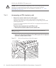
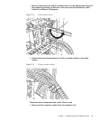
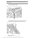
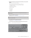
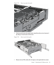
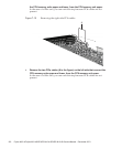
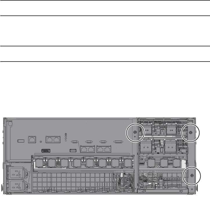
6.
Loosen the three screws holding the mounting fra me and th en remove i t.
Figure 7-8
Screws securing the mounting frame
Chapter 7 Maintaining the CPU Memory Units 95