


Note -
There is no problem if you remove the crossbar cables at the crossbar box while
electricity is supplied.
Note -
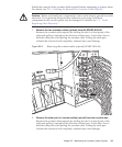
The cables at the rear of the crossbar box are bundled together and fastened to the
right-hand cable support with a hook-and-loop fastener. To remove the crossbar cables
(optical), therefore, remove the hook-and-loop fastener from the cable support.
Note -
There is no problem if you connect the crossbar cables (optical) at the crossbar box
while electricity is supplied.
Note -
If you insert a connector with the tab pulled, the connector may be damaged.
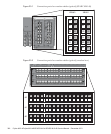
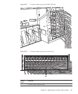
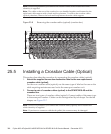
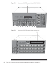
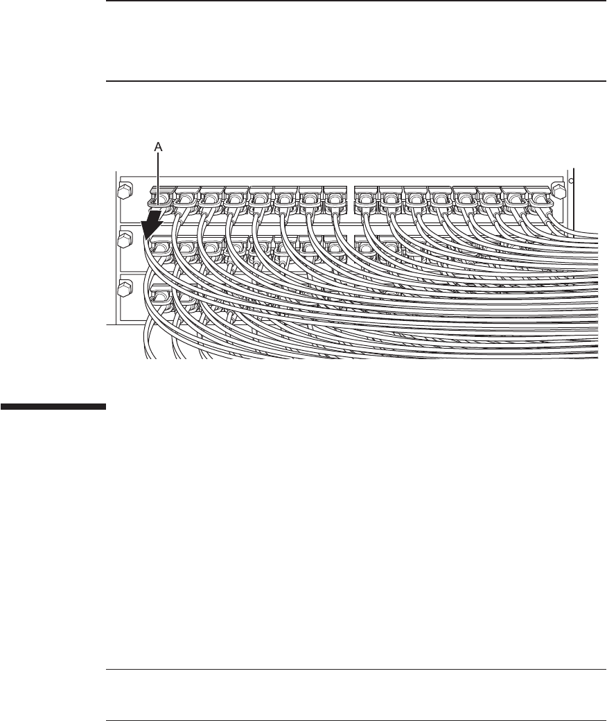
Figure 25-6
Removing the crossbar cables (optical) (crossbar box)
25.5 Installing a Crossbar Cable (Optical)
This section describes the procedure for connecting the crossbar cables (optical).
1.
Attach the supplied c onnection d estination label to the new replacement
crossbar cable (optical).
For the new crossbar cable (optical), use the same type of label as the one on the
cable requiring maintenance and write the same port number on it.
2.
Connect a pair of crossbar cables (optical) t o the SP A RC M10-4S and the
crossbar box.
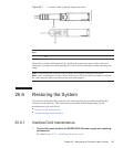
There are two types of crossbar cables (optical). Connect cables of the same type
to the same port number. Cables can be distinguished by tab shape. For the tab
shapes, see Figure 25-7.
Fujitsu M10-4/Fujitsu M10-4S/SPARC M10-4/SPARC M10-4S Service Manual
・
December 2013396