Front
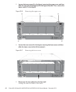
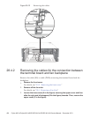
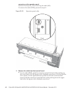
connector on t he operation panel.
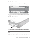
Perform this step only when removing the cable (SIG).
To remove the cable (PWR), proceed to step 10.
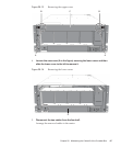
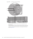
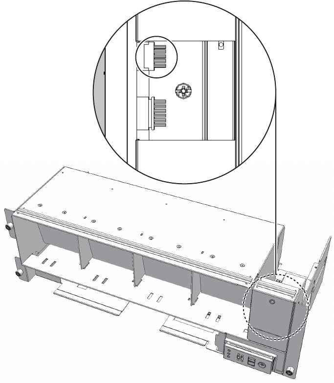
Figure 28-19
Operation panel cable
10.
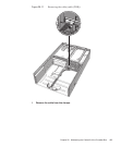
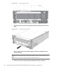
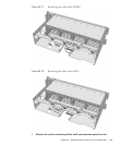
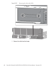
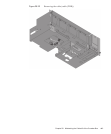
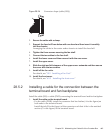
Remove the cable from the t erminal board.
■
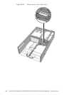
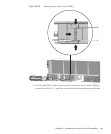
For the cable (PWR), push the connector toward the back while pushing up
the lower latch (A in the figure) with a flathead screwdriver. Confirm that the
lower latch (A in the figure) has been pushed to the back of the terminal
board. Push the connector toward the back while pushing down the upper
latch (B in the figure) with a flathead screwdriver.
Fujitsu M10-4/Fujitsu M10-4S/SPARC M10-4/SPARC M10-4S Service Manual
・
December 2013440


