


Note -
Mount the memory in the same position as it was mounted in the removed CPU
memory unit lower.
Note -
This work should all be performed from the rear of the rack.
Note -
Place the removed CPU memory unit lower on a grounded antistatic ESD mat.
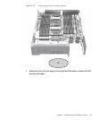
5.
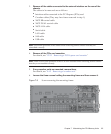
Remove the memory modules from the CPU m e mory unit low er and install
them in the new CPU memory un it l o w er.
For details, see "8.5 Removing Memory"and"8.6 Installing Memory."
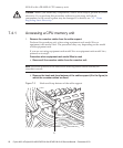
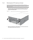
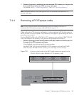
7.4.3 Removing the CPU memory unit upper
Removal of a CPU memory unit upper is performed after removal of the CPU
memory unit lower. Perform reduction using the same procedure. You can remove a
filler unit by performing the procedure up to step 9.
1.
Remove the CPU memory unit low er.
For details, see "7.4.2 Removing the CPU memory unit lower."
2.
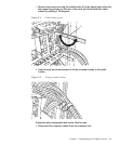
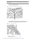
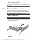
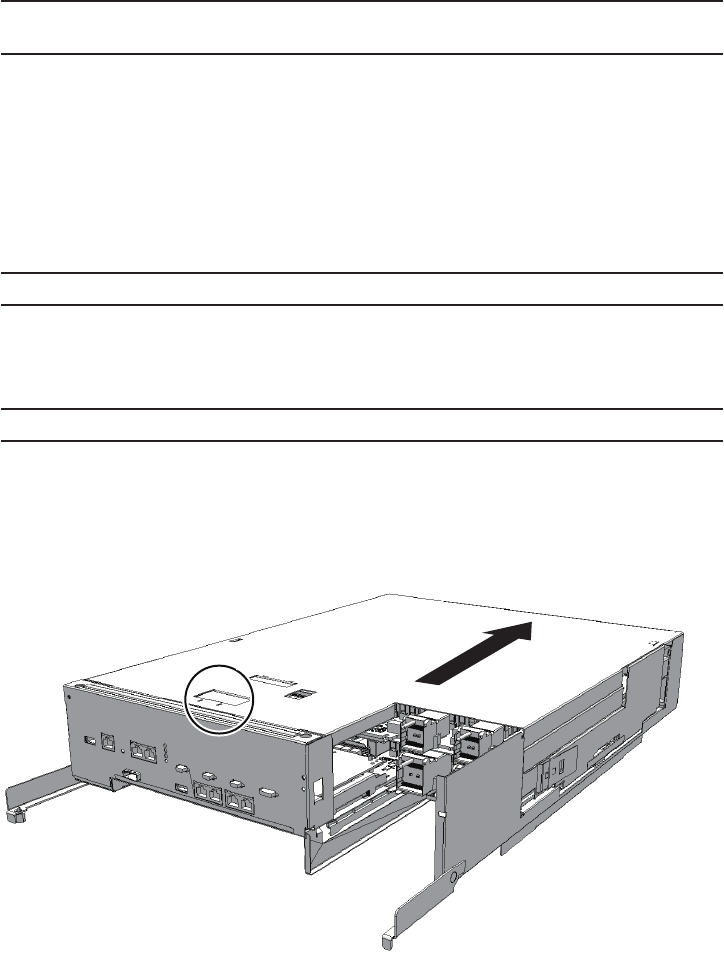
Unlock (push) the top cover of the CPU memory unit and rem ove t he cover b y
sliding it in the direction of the arrow.
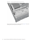
Figure 7-12
Releasing the lock
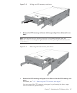
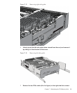
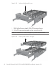
3.
Unlock (push) the right-side guide and re move it by sliding it in the direction
of the arro w.
Fujitsu M10-4/Fujitsu M10-4S/SPARC M10-4/SPARC M10-4S Service Manual
・
December 201398